Phase contrast cone-beam CT imaging

A cone beam, image technology, applied in the field of phase contrast imaging of technology, which can solve problems such as complex optical settings

Inactive Publication Date: 2010-01-06
UNIVERSITY OF ROCHESTER
View PDF1 Cites 11 Cited by
  • Summary
  • Abstract
  • Description
  • Claims
  • Application Information

AI Technical Summary

Problems solved by technology

These two methods not only require a synchrotron as a coherent monochromatic X-ray source, but also a relatively complex optical setup

Method used


Image

  • Phase contrast cone-beam CT imaging
  • Phase contrast cone-beam CT imaging
  • Phase contrast cone-beam CT imaging

Examples


Embodiment Construction

[0022] A preferred embodiment of the present invention will be specifically described below with reference to the accompanying drawings, wherein like numerals indicate like components or steps throughout.

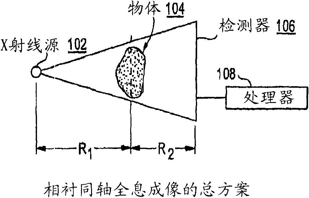
[0023] The structure of coaxial holography is as simple as that of current mammography or cone-beam CT protocols, as figure 1 shown. The microfocus X-ray source 102 is positioned at a distance R1 from an object 104 which is at a distance R from a detector 106 2 . The cone angle should cover the entire area of ​​interest. Processor 108 accepts detection data from detector 106 and performs the calculations described below to generate an image.

[0024] In X-ray technology, the refractive index n of a material is usually defined as:

[0025] n=1-δ+iβ (1)

[0026] where δ corresponds to the phase change and β is related to the attenuation. (Physically, δ is proportional to the electron density inside the material, which is usually 10 larger than β 3 to 10 4 times). Th...


PUM

PropertyMeasurementUnit
densityaaaaaaaaaa

Abstract

A cone beam CT imaging system incorporates the phase contrast in-line method, in which the phase coefficient rather than only the attenuation coefficient is used to reconstruct the image. Starting from the interference formula of in-line holography, the terms in the interference formula can be approximately expressed as a line integral that is the requirement for all CBCT algorithms. So, the CBCT reconstruction algorithms, such as the FDK algorithm, can be applied for the in-line holographic projections.

Description

[0001] References to related applications [0002] This application claims the benefit of US Provisional Patent Application No. 60 / 776,684, filed February 27, 2006, the disclosure of which is hereby incorporated by reference into this specification. [0003] Statement of Government Interest [0004] The work to develop this invention was supported in part by NIH Grants 8 R01 EB 002775, R01 9HL078181 and 4 R33 CA94300. The government has certain rights in this invention. technical field [0005] The present invention relates to phase contrast imaging, in particular phase contrast imaging using the technique of in-line holography. Background technique [0006] During the past few decades, phase contrast methods have developed rapidly in the field of X-ray imaging. Generally, X-ray images an object by obtaining only its attenuation coefficient map, while phase-contrast imaging images an object using both phase coefficient and attenuation coefficient. Therefore, in the pr...

Claims


Application Information

Patent Timeline
Patent Type & Authority Applications(China)
IPC IPC(8): G01N23/00G03H5/00G01N23/04G01N23/20G01T1/36G01N23/201
CPCG21K2207/005A61B6/484A61B6/032A61B6/4092A61B6/4085A61B6/508G01N2223/401
Inventor 宁若拉W·蔡
Owner UNIVERSITY OF ROCHESTER
Why Eureka
Try Eureka