
Vehicular visual assistance system

An auxiliary device and field of view technology, applied in vehicle parts, transportation and packaging, closed-circuit television systems, etc., can solve the problems of poor visual recognition of vehicle drivers, inability to obtain a sense of continuity, safety confirmation of hard-to-dead corners, etc.

Inactive Publication Date: 2010-01-13
HONDA LOCK MFG CO LTD
View PDF1 Cites 2 Cited by
  • Summary
  • Abstract
  • Description
  • Claims
  • Application Information

AI Technical Summary

Problems solved by technology

[0004] The side view of the vehicle driver on the driver's seat is a combination of the direct view on the front side viewed through the windshield, the indirect view on the rear side obtained through the door rearview mirror, and the image obtained by the camera device field of view, but for the above-mentioned existing solutions, there may be a dead angle between the direct field of view and the indirect field of view and the image obtained by the camera device, and it is difficult to confirm the safety of the blind angle
And because the direct field of view and the indirect field of view and the sense of continuity between the images cannot be obtained, the visual recognition effect of the vehicle driver is relatively poor

Method used


Image

  • Vehicular visual assistance system
  • Vehicular visual assistance system
  • Vehicular visual assistance system

Examples


Embodiment Construction

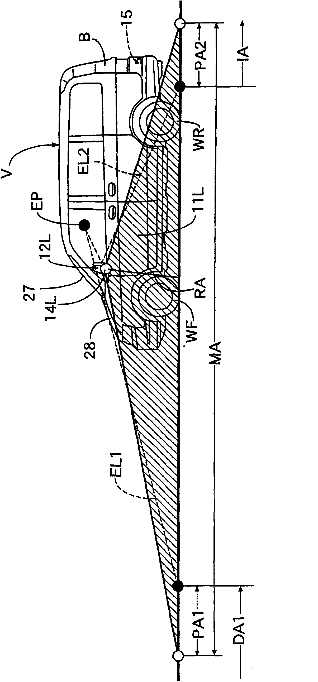
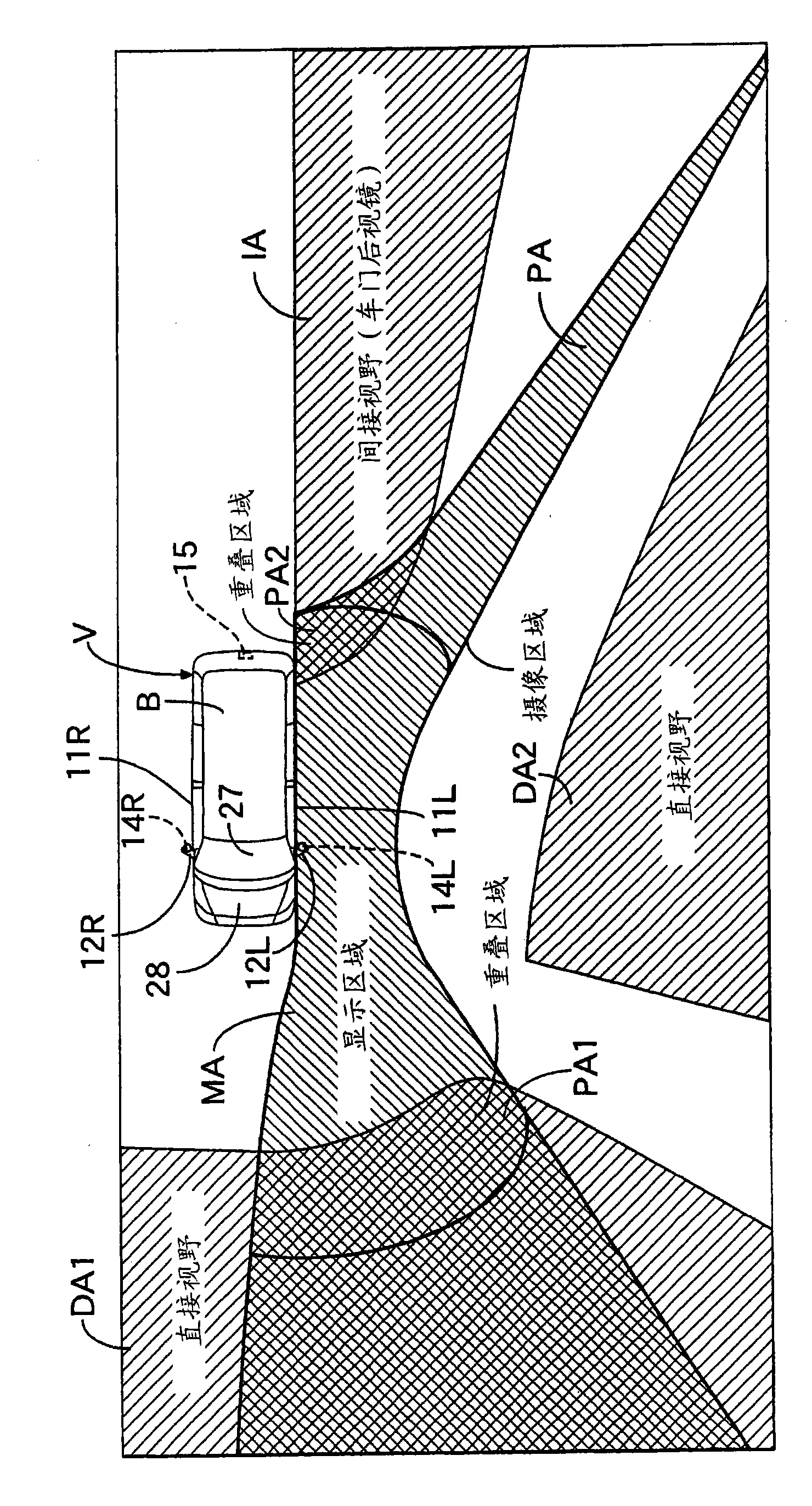
[0016] Refer below Figure 1 to Figure 11 Describe the first embodiment of the present invention, first in figure 1 and figure 2 Among them, left and right door mirrors 12L and 12R are respectively provided on a left front door 11L and a right front door 11R arranged on the left and right sides of the vehicle V. As shown in FIG. Left and right imaging devices 14L, 14R capable of imaging the side, front, and rear of the vehicle V are attached to these door mirrors 12L, 12R, respectively. At the lower part of the rear end of the vehicle body B, a rear imaging device 15 capable of imaging the rear of the vehicle V is attached.

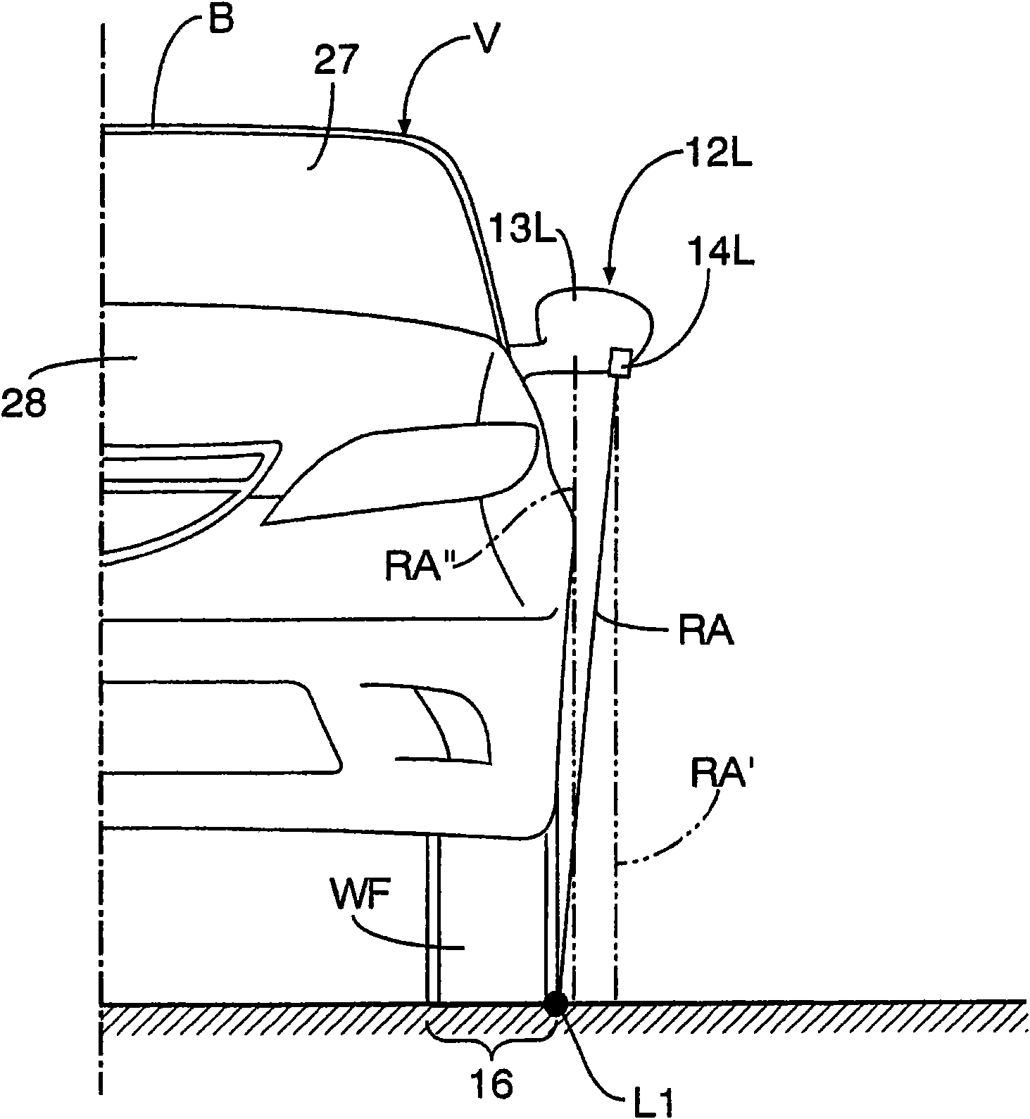
[0017] exist image 3 and Figure 4 Among them, the left and right imaging devices 14L, 14R are attached to the lower portions of the housings 13L, 13R of the left and right door mirrors 12L, 12R. The left imaging device 14L is mounted on the lower part of the housing 13L so that its optical axis RA intersects a straight line L1 passing through the ...


PUM


Abstract

In a vehicular visual assistance system, an image picked up by an image pickup device capable of picking up an image of a fore-and-aft region sideward of a vehicle is processed by an image processing device, and displayed on a display monitor. The image pickup device (14L) is mounted on a lower part of a door mirror housing, and is capable of picking up an image of a region that is continuous in the fore-and-aft direction while simultaneously including part of a front region directly viewed by a vehicle driver on a driver's seat and part of a rear region indirectly viewed by the vehicle driver via a door mirror. The image processing device displays, on the display monitor, a region for which at least front and rear boundaries thereof overlap the rear edge of the directly viewed region and the front edge of the indirectly viewed region, respectively. Thus, it is possible to avoid a blind spot from occurring between the direct and indirect views and the image based on the picked up image.

Description

[0001] This application is a divisional application of the Chinese invention patent application with the filing date of December 7, 2005, the title of the invention is "Vehicle Vision Assist Device", and the application number is 200510127478.1. technical field [0002] The invention relates to a vehicle field of vision assisting device, which comprises: an imaging device installed in a door rearview mirror housing capable of imaging the side of the vehicle front and rear; and a monitor installed in the vehicle for visual confirmation by the driver of the vehicle. and an image processing device for processing the imaging signal obtained by the imaging device and displaying the obtained image on the monitor. Background technique [0003] For example, in Japanese Patent Application Laid-Open No. 2002-67794, such an imaging device disposed at the bottom of the door mirror housing is disclosed, which simultaneously captures images in both the front and rear directions of the side...

Claims


Application Information

Patent Timeline
Patent Type & Authority Applications(China)
IPC IPC(8): B60R11/04H04N7/18
Inventor 久木田知之坂本博志
Owner HONDA LOCK MFG CO LTD
Features
  • Generate Ideas
  • Intellectual Property
  • Life Sciences
  • Materials
  • Tech Scout
  • Unparalleled Data Quality
  • Higher Quality Content
  • 60% Fewer Hallucinations
Learn More