
Solar efficient spotlighting system

A technology of concentrating lighting and sunlight, which is applied in the direction of light guides, lighting applications, lighting devices, etc. The effect of increasing the focal length of light, increasing the amount of concentrated light, and increasing the amount of light emitted

Inactive Publication Date: 2010-01-13
林于纮
View PDF0 Cites 5 Cited by
  • Summary
  • Abstract
  • Description
  • Claims
  • Application Information

AI Technical Summary

Problems solved by technology

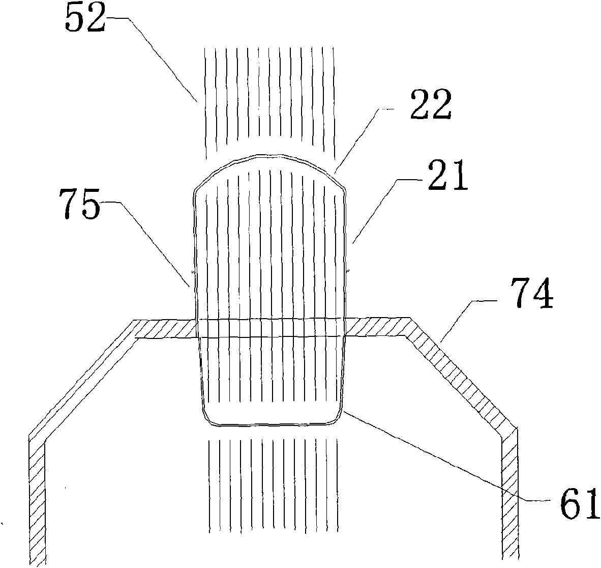
[0003] According to research, the conventional solar lighting lamps currently used are really overkill. The glass concentrator 22 and the concentrator 21 can withstand several times the sunlight, and can emit several times the illumination luminosity. The glass concentrator 22 is small, and the glass concentrator The cover receives less sunlight, and the lighting lamp 61 produces less luminosity. The light tube 75 is directly connected to the lighting lamp. The diameter of the light tube 75 is too thick to bend and turn.
[0004] The benefit rate of solar lighting lamps cannot be improved. Everyone knows that sunlight is green energy, inexhaustible and inexhaustible. It is an inexhaustible green light source that does not require money to buy. The diameter of the light tube 75 is too large, so the solar lighting has not been able to be effectively promoted, and everyone knows that the convex lens can concentrate light, but why no manufacturer has applied the convex lens to the solar concentrator, so it is generally used Solar lights have a lot of room for improvement

Method used


Image

  • Solar efficient spotlighting system
  • Solar efficient spotlighting system
  • Solar efficient spotlighting system

Examples


Embodiment Construction

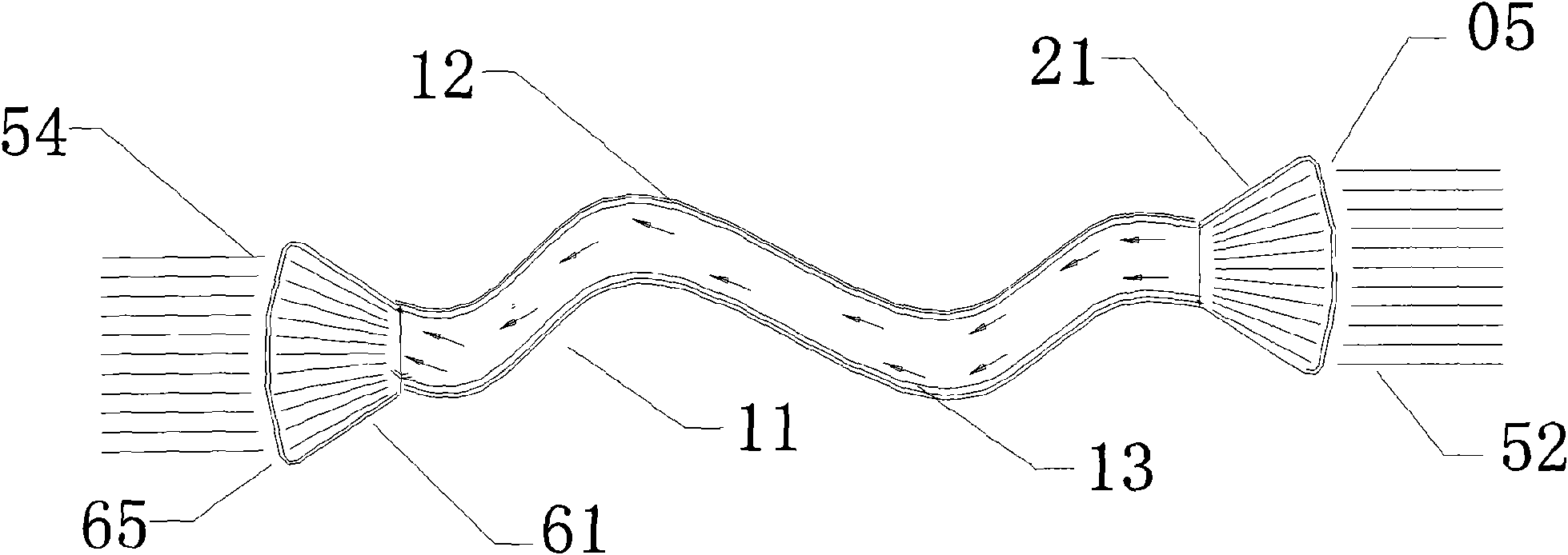
[0057] 1. The description of this case is as follows: Figure 8 : Schematic diagram of thinning convex lens. The thickness of the convex lens is thicker, the weight is larger, and the cost is higher, such as Figure 8-1 , the convex lens is cut into several concentric circles, and each concentric circle is adjusted to the same thickness. Although the luminosity is slightly lost, the thin flat mirror effectively reduces the thickness, such as Figure 8-2 , adjusting the ten concentric circles of the convex lens to have the same thickness can flatten the convex lens, such as Figure 8-3 , cutting the convex lens into more concentric circles can effectively thin the flat mirror. This thin flat mirror is commonly known as a Fresnel lens, and several thin flat mirrors are arranged in an arc. The curved surface is the curved flat compound eye condenser, such as Figure 8 -4. Cut the convex lens into twenty or more concentric circles, and rotate each concentric circle on a curved ...


PUM


Abstract

The invention aims to provide a spotlighting device for solving the problem of poor solar collecting efficiency, which uses a rotary ring light collecting mirror, a light collector, a hollow optical cable, an optical distributor and a light to solve the problem of poor solar collecting efficiency, thereby outputting many folds of luminosity by the solar spotlighting device. The solar efficient spotlighting system adopts the rotary ring optical collecting mirror to collect many times of sunlight to be transmitted and distributed by the hollow optical cable and the optical distributor, the light generates the sunlight for lightening, so that the sunlight can be guided to any places with random directions for generating many folds of the luminosity.

Description

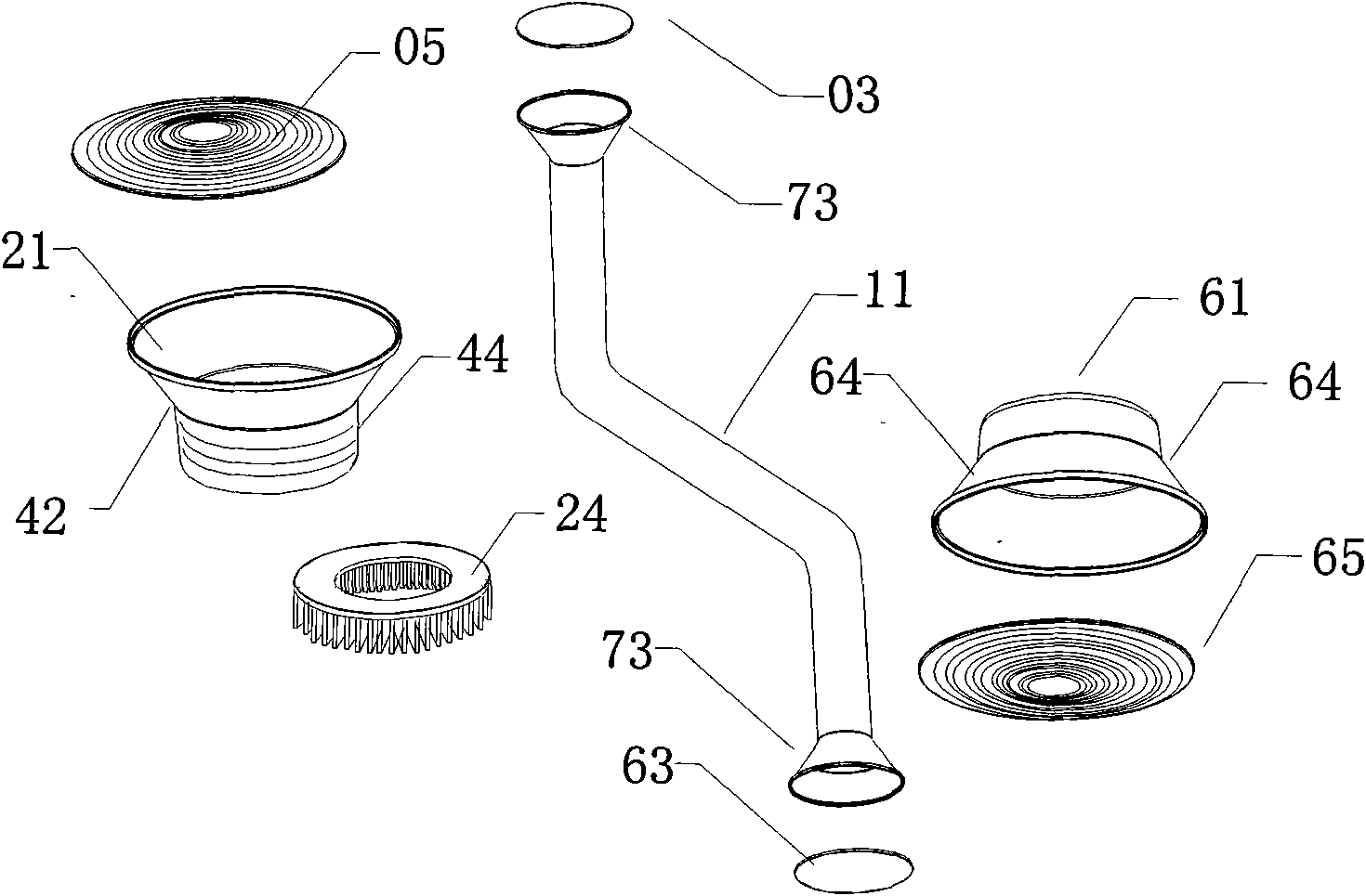
Technical field [0001] The present invention relates to a kind of solar lighting device, especially refers to the solar energy intensive spotlight lighting device with rotary ring condenser, hollow optical cable, light distributor and lighting lamp. The light collector is equipped with condenser and hollow optical cable. The hollow optical cable in the concentrator is used to transmit and distribute sunlight through the hollow optical cable and the light distributor, and the illuminating light is emitted by the lighting lamp for illumination, so that the sunlight can be redirected and directed to the desired place, and it can be gathered by a rotating ring condenser Several times the sunlight energy produces several times the sunlight illumination. Background technique [0002] Commonly used solar lighting lamps on the market, such as figure 2 : Conventional solar lighting, the concentrator 21 is directly facing the sunlight 52, the concentrator 22 is equipped with glass ab...

Claims


Application Information

Patent Timeline
Patent Type & Authority Applications(China)
IPC IPC(8): F21S19/00F21V13/00F21V8/00F21S9/02F21S9/03F21V23/00
Inventor 林于纮
Owner 林于纮
Learn More