
Position control method of servo motor

A technology of servo motor and control method, applied in the direction of position/direction control, electrical program control, non-electric variable control, etc., can solve problems such as inability to adapt to high-precision counting, inability to adapt to high-speed counting, inability to adapt to real-time requirements, etc., to meet the requirements The effect of reducing and increasing the number of counts and fast counting speed

Inactive Publication Date: 2011-04-13
NINGBO UNIV
View PDF0 Cites 0 Cited by
  • Summary
  • Abstract
  • Description
  • Claims
  • Application Information

AI Technical Summary

Problems solved by technology

Although the above-mentioned first method can effectively guarantee the counting accuracy of the number of pulses of the pulse signal, it can also meet the requirements of different counting digits by using counters with different digits, but in the case of a large number of counted pulses, The counter is required to have more digits, so the cost will increase sharply with the increase of the number of counter digits, and the counting speed will be greatly reduced with the increase of the number of counter digits, which cannot meet the requirements of high-speed counting; the second method is due to The counting control program is used, so unlike the counter in the first method, there is a limit on the number of digits, and the number of digits can be increased arbitrarily, which is suitable for the situation where a large number of pulses needs to be counted. Some counters count, so the hardware expenditure is greatly reduced, but the counting accuracy is not high when using the counting control program, which is a fatal flaw, which cannot meet the requirements of high-precision counting. The counting speed cannot meet the requirements of high-speed counting, nor can it meet the requirements of real-time

Method used


Image

  • Position control method of servo motor
  • Position control method of servo motor
  • Position control method of servo motor

Examples


Embodiment Construction

[0019] The present invention will be further described in detail below in conjunction with the accompanying drawings and embodiments.

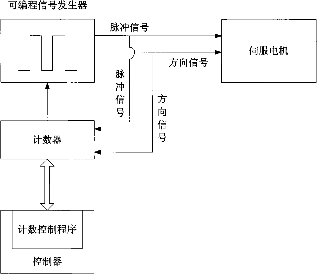
[0020] When controlling the position of the servo motor, if it is implemented purely using a counter, the counting speed will decrease with the increase of the number of counter digits, and at the same time it will increase the hardware cost. If it is implemented purely using a counting control program, there will be Counting accuracy is not high. In order to increase the counting speed while ensuring the counting accuracy, to meet the requirements of high-precision and high-speed counting, and reduce hardware costs, the invention proposes a servo motor position control method.

[0021] The inventive method is used to connect the programmable signal generator of pulse signal with servomotor and counter respectively, then counter is connected with a controller with counting control program, as figure 1 As shown, the programmable signal generat...


PUM


Abstract

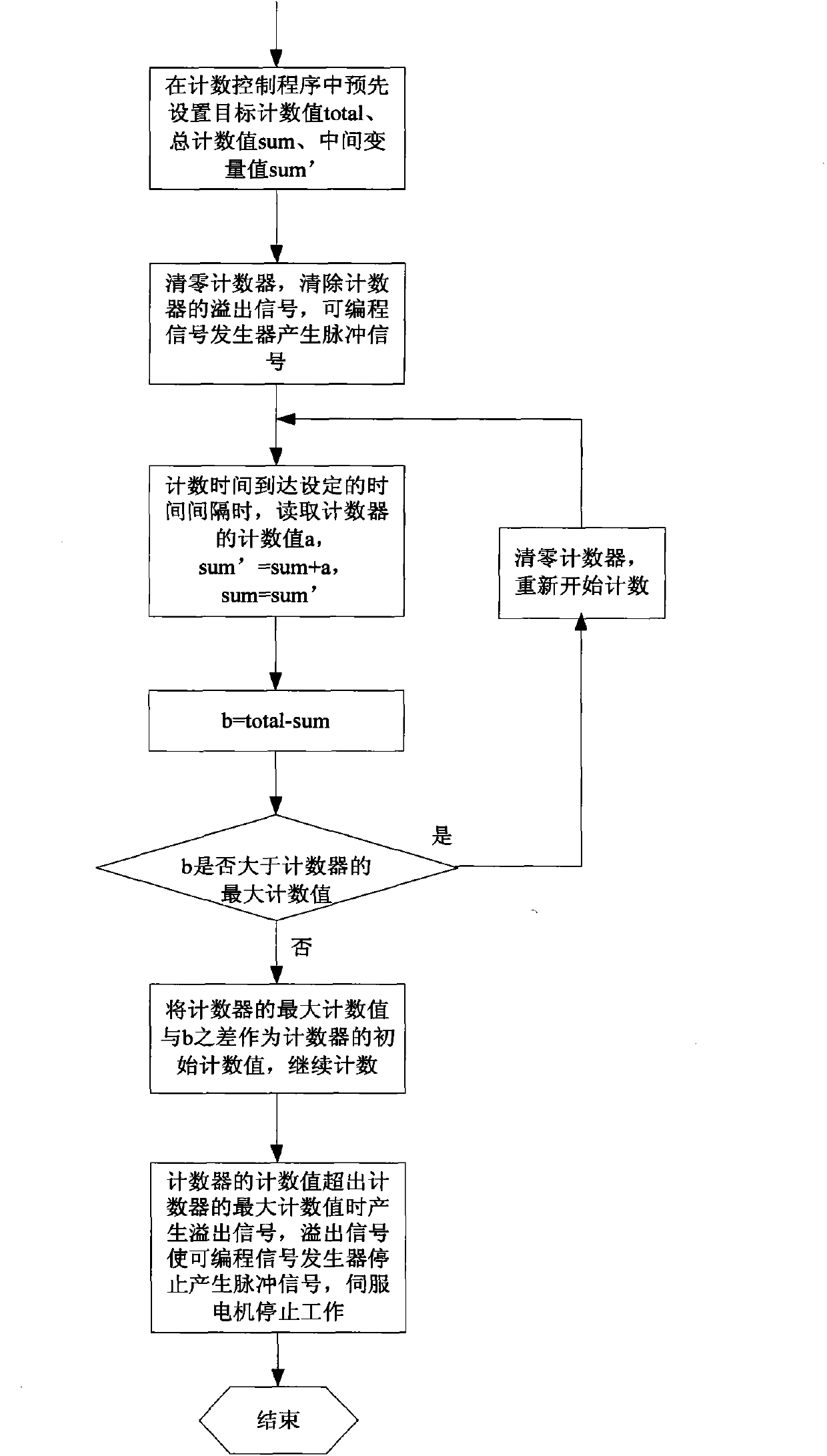
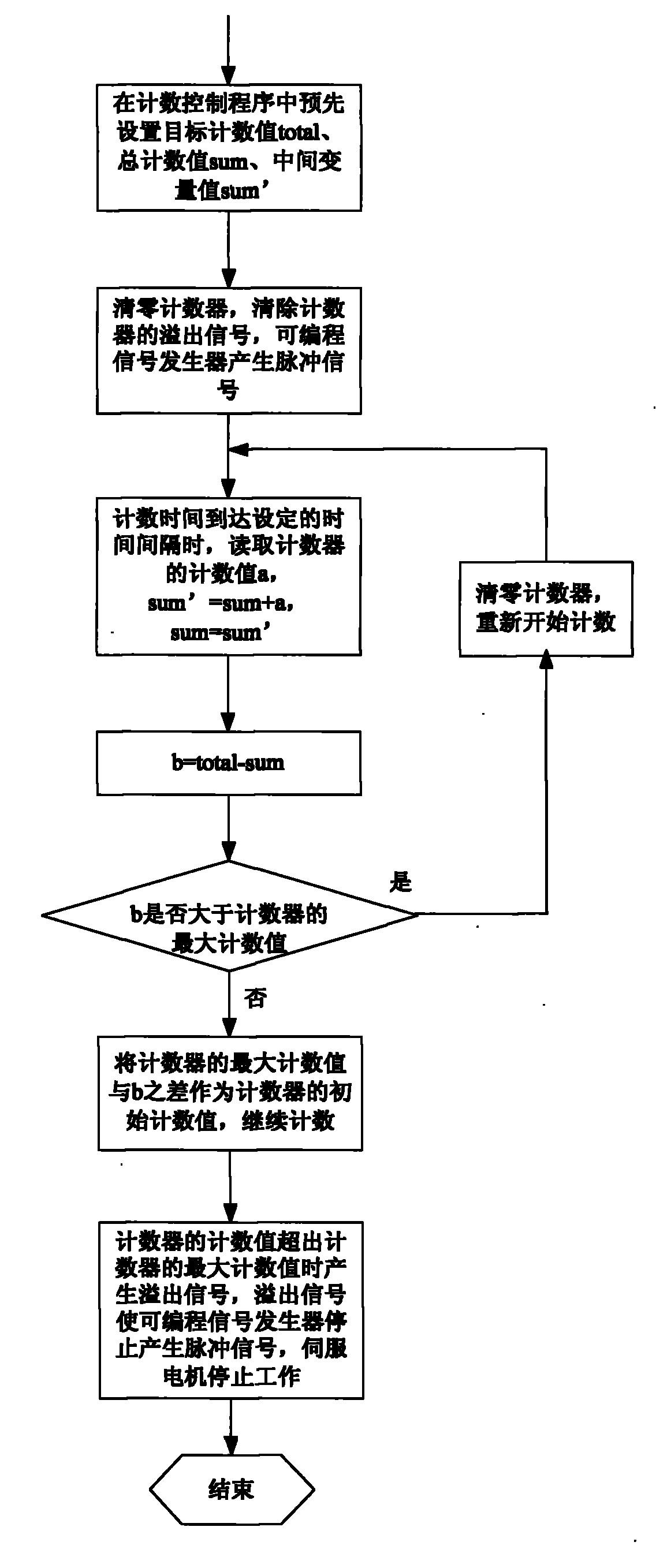
The invention discloses a position control method of a servo motor. When the difference of a target counting value and a counted total numerical value is greater than the maximum counting value of a counter, a counting control program controls the counter to reset and restart to count by combining and using the counter and the counting control program and setting the target counting value in the counting control program in advance; when the difference of the target counting value and the counted total numerical value is smaller than or equal to the maximum counting value of the counter, the counting control program controls the counter to take a result obtained by subtracting the difference of the target counting value and the counted total numerical value by the maximum counting value ofthe counter as a counting initial value and continue to count; and when the counting value of the counter exceeds the maximum counting value of the counter, the counter generates an overflow signal, so that the counting of the pulse number is realized by the matching of the counter and the counting control program. The invention ensures the counting accuracy, effectively enhances the counting speed, satisfies the requirement of counting with high accuracy and high speed and also lowers the hardware cost.

Description

technical field [0001] The invention relates to a servo motor control method, in particular to a servo motor position control method. Background technique [0002] Servo motors, also known as executive motors, are used as actuators in automatic control systems. Servo motors have the advantages of high precision, fast speed, high reliability, and good operability. [0003] The servo motor is generally driven by a pulse signal, and its rotation angle is determined by the number of pulses of the pulse signal, which requires a high-precision counter to accurately count the number of pulses of the pulse signal to determine the position of the servo motor , At the same time, due to the large number of pulses that may be counted, the high-precision counter is required to have a large number of digits at the same time. At present, two methods are usually used to count the number of pulses of pulse signals. The first method is to directly use a commercially available counter and con...

Claims


Application Information

Patent Timeline
Patent Type & Authority Patents(China)
IPC IPC(8): G05B19/05G05D3/00
Inventor 俞建定徐铁峰蒋刚毅叶军严洁卿
Owner NINGBO UNIV
Learn More