Permanent direct-current electric welding and electricity generating multipurpose machine

A permanent magnet direct current, multi-purpose technology, applied in the direction of electromechanical devices, electrical components, electric components, etc., can solve the problems of complex structure, failure to consider the heat dissipation of the motor, and the loss of magnetism of the magnetic steel

Active Publication Date: 2010-01-13
福建福凯电气有限公司
View PDF1 Cites 2 Cited by
  • Summary
  • Abstract
  • Description
  • Claims
  • Application Information

AI Technical Summary

Problems solved by technology

At present, this kind of products can be mainly divided into two types: one is the self-excited electric welding and power generation prototypes made of common magnetic materials. Because of their large size, complex structure, high energy consumption and low efficiency, they will be gradually eliminated by the market.
The other is an electric welding and power generation machine made of permanent magnet materials, such as a "DC welding, power generation, and charging multi-purpose machine" disclosed in Chinese utility model patent ZL 200520023786.5. The stator winding of this generator includes two three-phase electric welding Windings, a three-phase generating winding and a single-phase charging winding are all output after full-wave rectification. Because there are too many stator windings of this kind of generator, the wire diameter of the winding is greatly limited in a limited space, so the electric welding winding It is difficult to be suitable for high-current welding conditions; in addition, the structure of this type of generator does not take into account the heat dissipation of the motor. If the temperature of the rectifier is too high, the two headers will break down, and the overheating of the permanent magnet rotor will cause the magnet. The steel gradually loses magnetism, thereby reducing the service life of the generator, all of which will affect the market promotion of this kind of generator

Method used


Image

  • Permanent direct-current electric welding and electricity generating multipurpose machine
  • Permanent direct-current electric welding and electricity generating multipurpose machine
  • Permanent direct-current electric welding and electricity generating multipurpose machine

Examples


Embodiment Construction

[0010] The present invention will be further described below in conjunction with the accompanying drawings and embodiments.

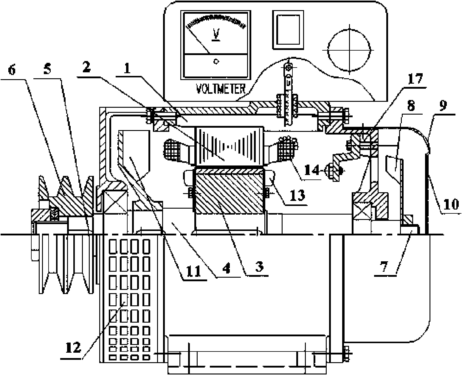
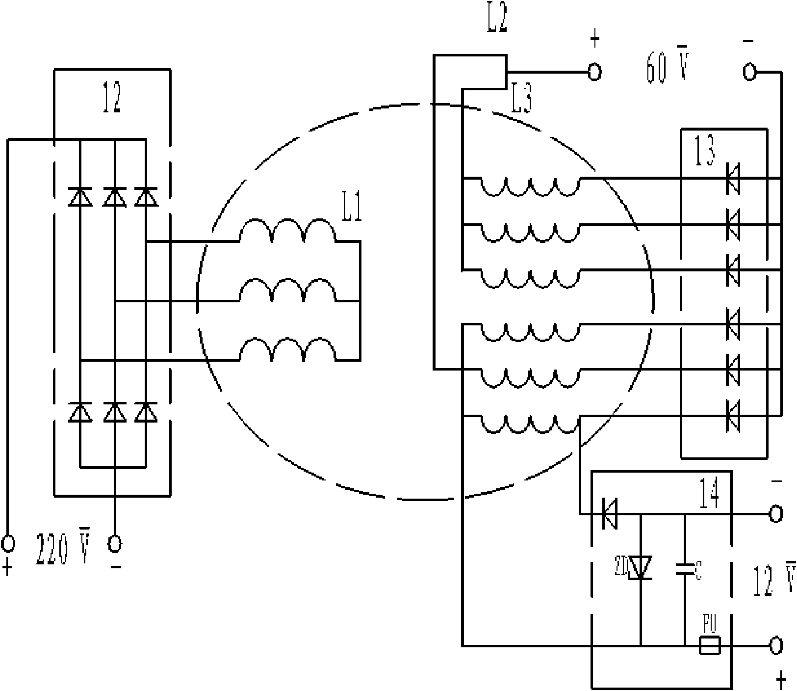
[0011] Such as figure 1 with figure 2 As shown, the present invention provides a kind of permanent magnet direct current electric welding, generating multi-purpose machine, comprises the stator 2, the rotor 3 with machine base 1, is characterized in that: the protruding end 5 of described rotor rotating shaft 4 is provided with pulley 6, The other end 7 of the rotating shaft is provided with an air inlet rotating blade 8, the corresponding end of the casing 9 is provided with an air inlet vent 10, and the side of the rotating shaft near the pulley is provided with a radial wind blade 11 located in the casing, and the machine Heat dissipation holes 12 are provided on the corresponding sides of the shell, radial wind deflecting blades 13 are also provided on the front and rear ends of the rotor, and radial wind guide vanes 14 are fixedly connected to th...


PUM


Abstract

The invention relates to a permanent direct-current electric welding and electricity generating multipurpose machine which comprises a rotor and a stator with a machine seat. An extending end of the rotating shaft of the rotor is provided with a belt pulley; the other end part of the rotating shaft is provided with an air inlet rotary vane; a machine shell is provided with an air inlet port corresponding to the end part; one side of the rotating shaft close to the belt pulley is provided with a radial vane positioned in the machine shell; a corresponding side part of the machine shell is provided with a radiating hole; the front end part and the rear end part of the rotor are also provided with radial torsion vane; and a corresponding side of an outer stator is fixedly connected with a radial air guiding vane. The permanent direct-current electric welding and electricity generating multipurpose machine has the advantages of small volume, little excitation loss, simple structure and small ripple factor of output voltage and solves the problem of arc interruption in electric welding.

Description

technical field [0001] The invention relates to a permanent magnet rotor generator, in particular to a multi-purpose machine for direct current welding, power generation and charging. Background technique [0002] Welding and power generation multi-purpose machines are favored by the market because of their built-in multiple voltage power supplies, which are very suitable for field operations without power supplies and in places with strong mobility. At present, this kind of products can be mainly divided into two types: one is the self-excited electric welding and power generation prototypes made of common magnetic materials. Because of their large size, complex structure, high energy consumption and low efficiency, they will be gradually eliminated by the market. . The other is an electric welding and power generation machine made of permanent magnet materials, such as a "DC welding, power generation, and charging multi-purpose machine" disclosed in Chinese utility model ...

Claims


Application Information

Patent Timeline
Patent Type & Authority Applications(China)
IPC IPC(8): H02K7/10H02K9/06H02K5/20H02K3/28H02K11/00
Inventor 陈兰生罗铃兴陈志坚陈万年
Owner 福建福凯电气有限公司
Why Eureka
Try Eureka