Track slab grinder

A track plate and grinding machine technology, which is applied to grinding machines, machine tools suitable for grinding workpiece planes, grinding/polishing equipment, etc., can solve the problems of complicated mechanism, difficulty in ensuring accuracy, and rotating mechanism that affects grinding efficiency. Improve rigidity and bending resistance, eliminate tool mark error, and save movement time

Active Publication Date: 2010-01-20
四川省宜宾普什集团有限公司
View PDF0 Cites 17 Cited by
  • Summary
  • Abstract
  • Description
  • Claims
  • Application Information

AI Technical Summary

Problems solved by technology

The main function of the special CNC grinding machine for track slabs is to grind the track slab bearing platform. This kind of grinding machine has the characteristics of huge structure, complex mechanism, multiple functions, and high rigidity requirements. It has high technical content and is very difficult to develop.
Moreover, due to the use of an electric spindle for this kind of special CNC grinding machine for track plates, limited by the power of the electric spindle, the grinding of the rail bearing table needs to be divided into two processings, that is, the grinding wheel first performs unilateral grinding on the rail bearing table, and then unilaterally grinds the rail bearing table. Finally, the main shaft needs to be rotated 180° to grind the other side of the rail platform. Even if it is equipped with a double-sided grinding wheel, due to the limitation of the spindle power, the double-sided grinding of the rail platform cannot be performed at one time. Affects the grinding efficiency and increases the rotation mechanism, making the mechanism complicated
Due to the limitation of the structure, the overall rigidity of this special CNC grinding machine for track plates is low, and the accuracy is not easy to guarantee

Method used


Image

  • Track slab grinder
  • Track slab grinder
  • Track slab grinder

Examples


Embodiment Construction

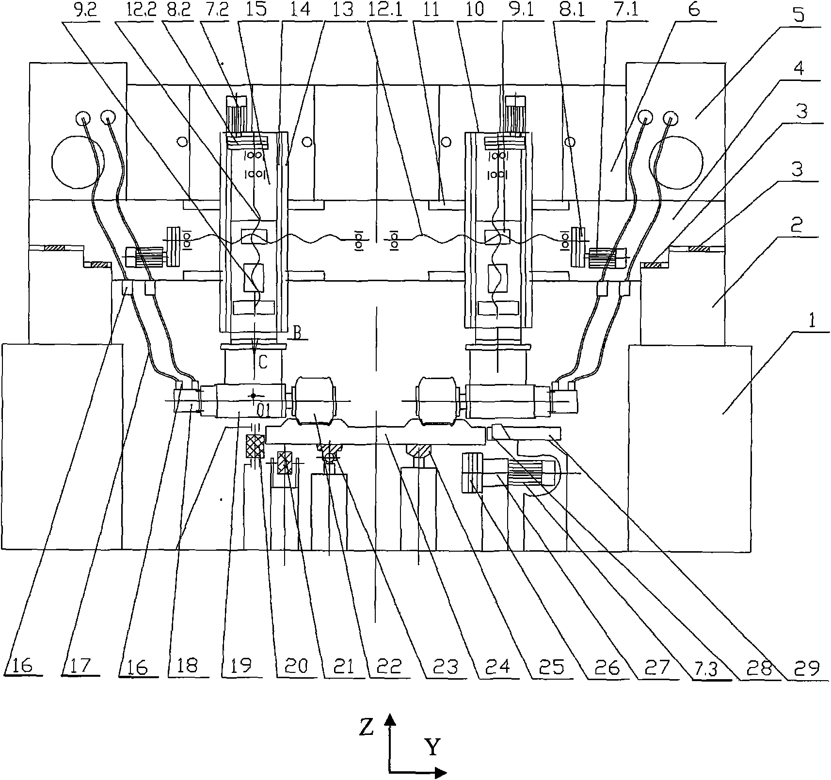
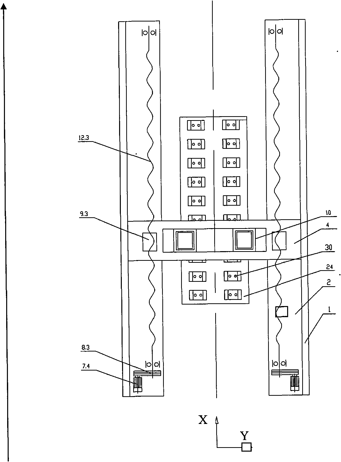
[0018] see figure 1 with figure 2 , the present invention comprises the wall plate type elevated gantry structure and left and right grinding wheel 22 that left and right main base walls 1 constitute. The key technology is to install the left and right main longitudinal beams 2 on the left and right main foundation walls 1 respectively, install two main longitudinal guide rails 3 on the main longitudinal beams 2 to form a ladder shape, and install boxes between the main longitudinal guide rails 3 The main beam 4 of the shaped beam structure is such that the main beam 4 is supported on the main longitudinal beam 2 through the main longitudinal guide rail 3, and the main beam 4 constitutes a full-frame symmetrical four-rail structure. The driving device of main beam 4 comprises servo motor 7.4 and leading screw 12.3, and servo motor 7.4 connects belt pulley 8.3, and belt pulley 8.3 connects leading screw 12.3, and leading screw 12.3 is connected with main beam 4 by nut 9.3. T...


PUM


Abstract

The invention is a track slab grinder, and relates to a special grinder for grinding a track slab. The track slab grinder comprises left and right main foundation walls and left and right grinding wheels. The key technology thereof is as follows: the left and right main foundation walls are respectively provided with a main longitudinal girder provided with a main longitudinal guide rail, a main transverse beam is arranged between the main longitudinal guide rails and is provided with left and right transverse guild rails respectively, the transverse guild rail is installed with a transverse sliding box which is internally provided with a vertical guild rail, an inner box is mounted on the vertical guild rail, a main shaft direction adjusting box is arranged at the lower end part of the inner box, a grinding head is arranged at the lower side of the main shaft direction adjusting box, a grinding wheel is mounted on the main shaft of the grinding head, and the main shaft of the grinding head is driven by a hydraulic motor. The track slab grinder in the invention can finish processing both sides of a bearing block at one time, has the advantages of high integral strength, stable movement, good rigidity, high processing efficiency, and can process a standard track slab as well as a track slab grinder of a non-standard track slab.

Description

Technical field: [0001] A track plate grinder relates to a special grinder for grinding track plates. Background technique: [0002] Due to the high-speed running of trains, some railway rails are not laid on ordinary sleepers, but on track slabs precisely ground by machine tools. Each track slab is composed of 2 rows of rail bearing platforms. There are standard track slabs and non-standard track slabs. Standard track slabs and non-standard track slabs not only have different numbers of rail bearing platforms, but also have different directions (different coordinate values ​​and angle values). The main function of the special CNC grinding machine for track slabs is to grind the track slab bearing platform. This kind of grinding machine has the characteristics of huge structure, complex mechanism, multiple functions, and high rigidity requirements. It has high technical content and is very difficult to develop. . Moreover, due to the use of an electric spindle for this ki...

Claims


Application Information

Patent Timeline
Patent Type & Authority Applications(China)
IPC IPC(8): B24B7/10B28D1/18
Inventor 李培奇吴元文柯坚陈玉良邓斌王健于兰英王家力刘斌
Owner 四川省宜宾普什集团有限公司
Why Eureka
Try Eureka