
Pressurizing cylinder

A pressurized cylinder and pressurized piston technology, applied in the field of hydraulic pressurized cylinders, can solve the problems of complex structure, large size and weight, difficult manufacture and maintenance, etc.

Active Publication Date: 2012-06-06
CHANGZHOU RUITAI ENG MASCH CO LTD +1
View PDF8 Cites 0 Cited by
  • Summary
  • Abstract
  • Description
  • Claims
  • Application Information

AI Technical Summary

Problems solved by technology

At present, the existing domestic rail welding equipment can only weld long rails below 100 meters due to insufficient clamping force, which cannot meet the needs of welding long rails of 500 meters or longer and lock welding
Chinese patent application No. 98106266.0 discloses a kind of booster pressurized oil cylinder in the flash butt welding rail welder application document of 98106266.0. Maintenance; due to the special guide part on the oil cylinder, the structure is more complicated, the size and weight are large, the manufacture is difficult, and the guide part has the risk of oil leakage
In addition, it cannot control the output clamping force, which is not convenient for construction operation

Method used


Image

  • Pressurizing cylinder
  • Pressurizing cylinder
  • Pressurizing cylinder

Examples


no. 1 example

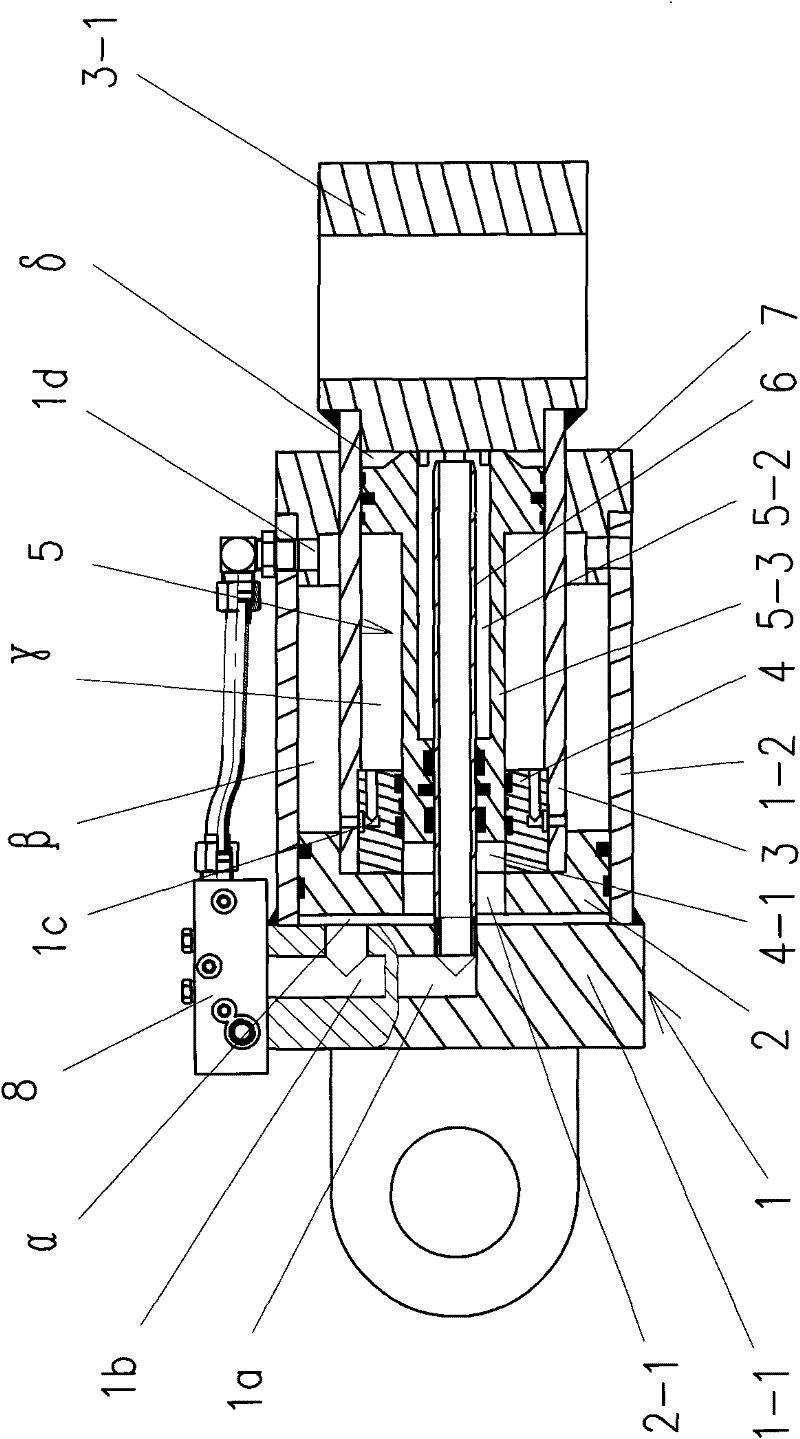
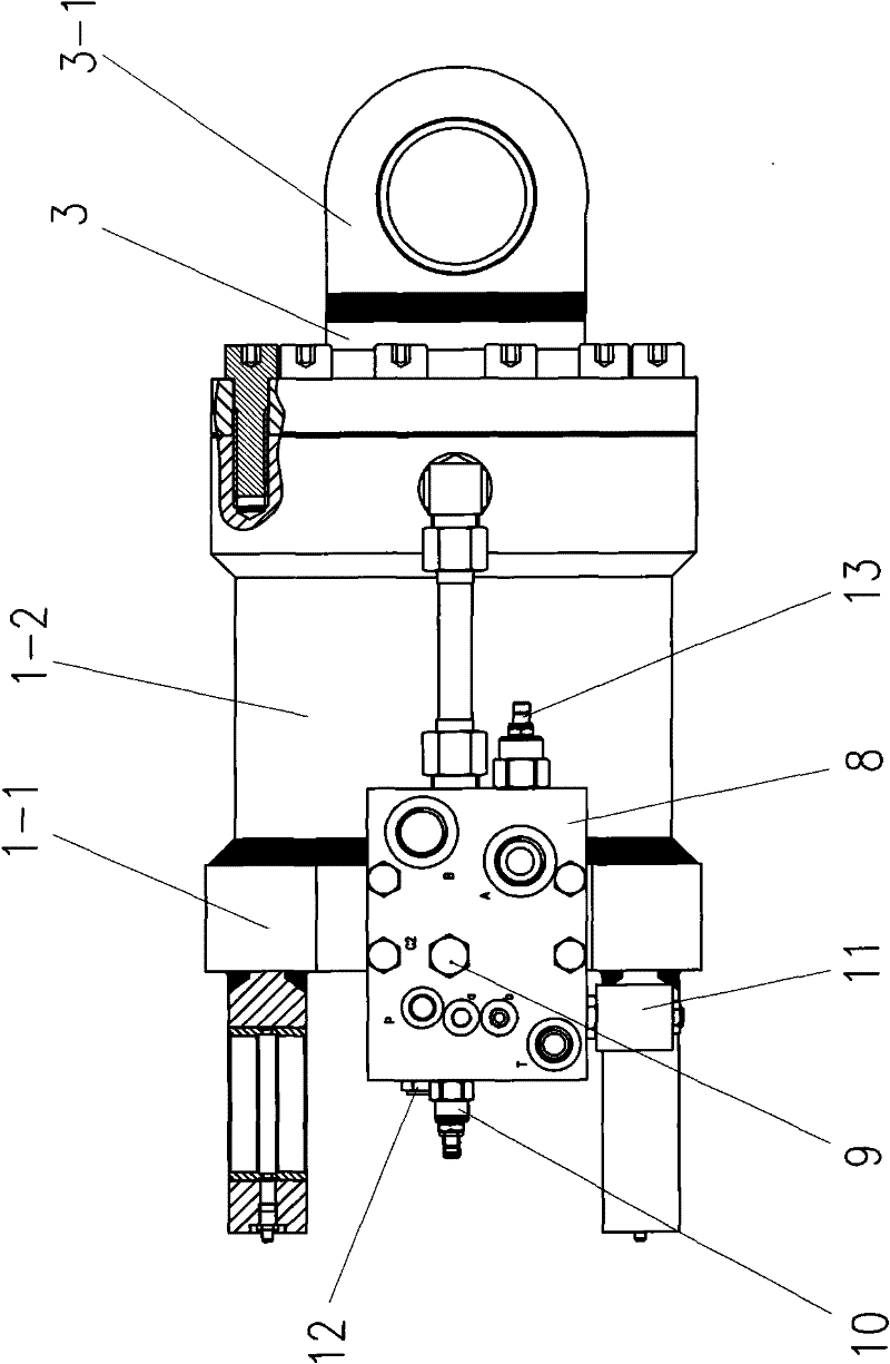
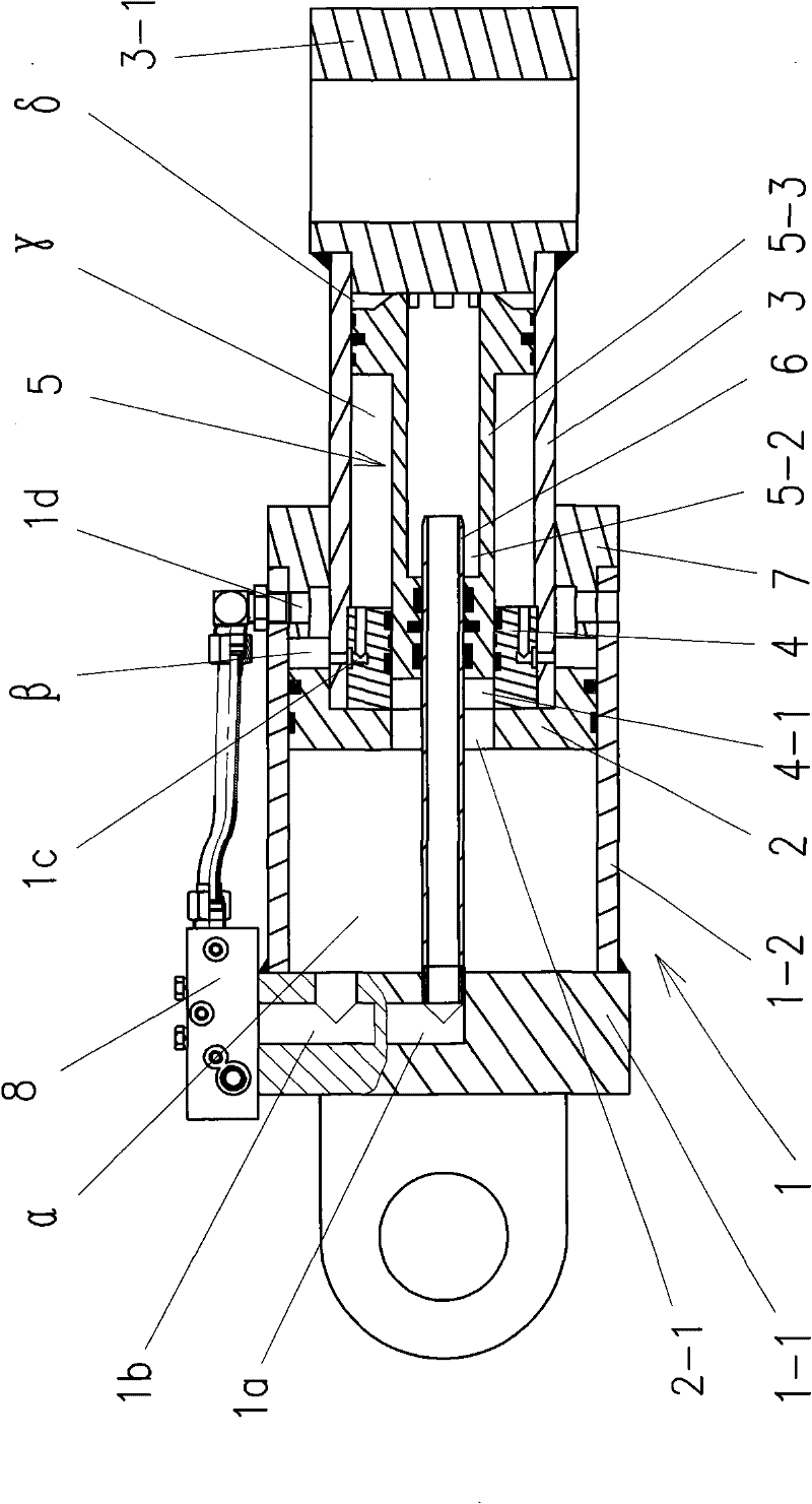
[0021] Such as figure 1 , 2 , 3, and 5 are the first embodiment of the present invention, a pressurized oil cylinder, including cylinder 1, piston 2, piston rod 3, piston rod end connector 3-1 and end cover 7, cylinder 1 The inner cavity of the piston 2 is divided into a first cavity α and a second cavity β, the piston rod 3 is equipped with a booster piston 5, and the inner cavity of the piston rod 3 is divided into a third cavity γ and a fourth cavity δ by the booster piston 5. The second cavity β and the third cavity γ are communicated through the oil passage 1c, and the piston 2 has an opening 2-1. One end of the booster piston 5 can penetrate through the opening 2-1 of the piston 2 and extend into the cylinder 1 The first cavity α, the booster piston 5 has a through hole 5-2, the through hole 5-2 communicates with the fourth cavity δ of the inner cavity of the piston rod 3, and the end 1-1 of the cylinder 1 has a first oil passage 1a and The second oil circuit 1b is connec...


PUM


Abstract

The invention discloses a pressurizing cylinder which comprises a cylinder body, a piston, a piston rod, a piston rod end connecting piece and an end cover, wherein the piston rod is internally provided with a pressurizing piston, the piston is provided with an opening, one end of the pressurizing piston can penetrate out of the opening of the piston and extend into a first cavity of the cylinderbody, the pressuring piston is provided with a through hole, the through hole is communicated with a fourth cavity of an inner cavity of the piston rod, the end part of the cylinder body is provided with a first oil path and a second oil path, one end of the first oil path and one end of the second oil path are both led into a hydraulic integration block, the outlet of the other end of the first oil path is provided with an oil leading pipe, the overhang end of the oil leading pipe passes through the opening of the piston and enters into the through hole of the pressure piston to be communicated with the fourth cavity of the inner cavity of the piston rod, the periphery of the oil leading pipe and the through hole of the pressurizing piston at least keep a section of sealed sliding matching, the other end of the second oil path is led into the first cavity of an inner cavity of the cylinder body, and a second cavity of the inner cavity of the cylinder body is communicated with the hydraulic integration block through a third oil path. The invention has simple structure, convenient manufacture and adjustable clamping force.

Description

Technical field [0001] The invention relates to a clamping device of a rail flash welding machine, in particular to a hydraulic booster cylinder. Background technique [0002] The seamlessness of the railway line eliminates the joints of the steel rails, and also eliminates the impact and vibration between the wheels and the rail seams during the running of the train, prolongs the service life of the wheel and rail components, and reduces maintenance costs. At present, the existing domestic rail welding equipment, due to insufficient clamping force, can only weld long rails under 100 meters, and cannot meet the needs of welding long rails of 500 meters or longer and lock welding. Chinese Patent Application No. 98106266.0 Flash Butt Welding Rail Welding Machine Application Document discloses a booster pressurized oil cylinder. Although it can boost the force, its control valve is mounted on the connecting piece at the end of the piston rod. The structure is complex and difficult t...

Claims


Application Information

Patent Timeline
Patent Type & Authority Patents(China)
IPC IPC(8): F15B15/16F15B3/00
Inventor 宋自帅黄腾飞曹志国王有虹夏青顺郦雪云刘晓磊
Owner CHANGZHOU RUITAI ENG MASCH CO LTD
Learn More