Laser light four-dimensional imaging device based on optical fiber image convertor and multi-slit streak tube

An imaging device and converter technology, applied in the field of photoelectric detection, can solve the problems of small field of view, inability to reflect distance information, time information resolution, etc.

Inactive Publication Date: 2010-01-20
HARBIN INST OF TECH
View PDF0 Cites 18 Cited by
  • Summary
  • Abstract
  • Description
  • Claims
  • Application Information

AI Technical Summary

Problems solved by technology

[0003] The purpose of the present invention is to solve the problem that the current photodetector can only distinguish the spatial information of the object to be detected but cannot distinguish the time information at the same time, so it cannot reflect the distance information of the measured object, or the measured object can be obtained by scanning. The four-dimensional information of the object has a low frame frequency and a small field of view. A laser four-dimensional imaging device based on an optical fiber image converter and a multi-slit striped tube that can achieve time, space and intensity resolution is provided.

Method used


Image

  • Laser light four-dimensional imaging device based on optical fiber image convertor and multi-slit streak tube
  • Laser light four-dimensional imaging device based on optical fiber image convertor and multi-slit streak tube
  • Laser light four-dimensional imaging device based on optical fiber image convertor and multi-slit streak tube

Examples


specific Embodiment approach 1

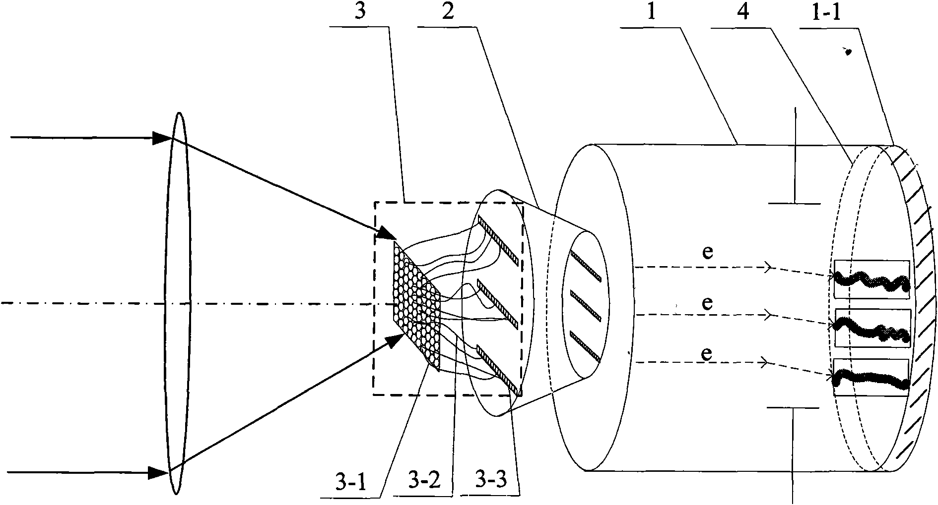
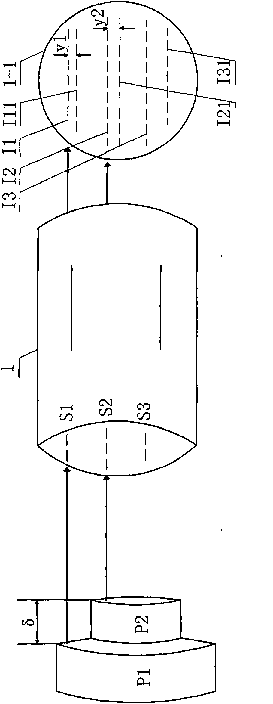
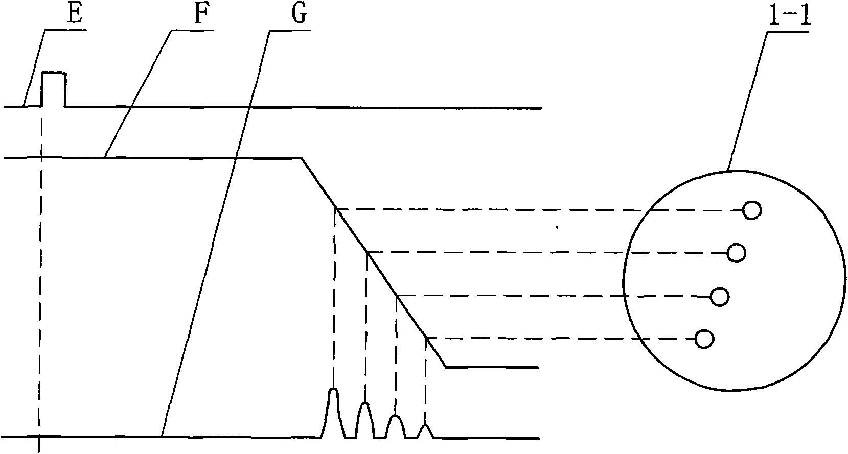
[0015] Specific implementation mode one: the following combination figure 1 , figure 2 and image 3 Describe this embodiment, this embodiment comprises multi-slit striped tube 1 and light cone 2, and it also comprises optical fiber image converter 3 and image intensifier 4, and optical fiber image converter 3 consists of input end panel 3-1, optical fiber group 3- 2 and the output end panel 3-3, the optical fiber group 3-2 is composed of 48×48 optical fibers of equal length, and one end of the optical fiber group 3-2 is arranged in the first array A of 48×48 on the input end panel 3-1 The other end of the optical fiber group 3-2 is arranged in the second array B of 8×288 on the output panel 3-3, and the arrangement of the first array A is as follows:

[0016] A = a 1 - 1 ...

specific Embodiment approach 2

[0032] Embodiment 2: The difference between this embodiment and Embodiment 1 is that the length of each optical fiber in the optical fiber group 3-2 is 10-90 cm. Other components and connections are the same as those in Embodiment 1.

specific Embodiment approach 3

[0033] Embodiment 3: The difference between this embodiment and Embodiment 1 or 2 is that the taper of the light cone 2 is 3:1. Other compositions and connections are the same as those in the first or second embodiment.


PUM


Abstract

A laser light four-dimensional imaging device based on an optical fiber image convertor and a multi-slit streak tube belongs to the photoelectric detection field. The imaging device solves the problem that the existing photoelectric detector can not reflect the range information of an object to be measured because the existing photoelectric detector only can distinguish the space information of a target detecting object and can not simultaneously distinguish the time information, or obtains the four-dimensional information of the object to be measured in a scanning mode but the frame frequency is lower and simultaneously the viewing field is smaller. An optical fiber group of the imaging device comprises 48*48 equal-length optical fibers; one ends of the optical fiber group are arranged on an input end panel in a 48*48 firs array A mode; and the other ends of the optical fibers are arranged on an output end panel in a 8*288 second array B mode; the output end panel is coupled with the big end of a light cone; the small end of the light cone is coupled with a photoelectricity negative pole of the multi-slit streak tube; the output end of an image intensifier is coupled with the input end of a fluorescent screen of the multi-slit streak tube. The imaging device is used for the four-dimensional imaging of objects to be detected.

Description

technical field [0001] The invention relates to a laser four-dimensional imaging device based on an optical fiber image converter and a multi-slit stripe tube, which is a laser four-dimensional imaging technology and belongs to the field of photoelectric detection. Background technique [0002] At present, various laser and infrared photoelectric imaging systems based on area array photodetectors have been widely used in various fields such as geological exploration, forest and agricultural census, marine monitoring, road and traffic monitoring, aircraft obstacle avoidance and navigation control, etc. important role. Because the traditional area array photodetector can only obtain the intensity information and two-dimensional spatial information of the target, that is, it can only obtain the two-dimensional plane image of the target, which makes it subject to certain limitations in practical applications, and sometimes it cannot fully reflect the measurement object The actu...

Claims


Application Information

Patent Timeline
Patent Type & Authority Applications(China)
IPC IPC(8): G01S17/89G01S7/481
Inventor 王骐李思宁刘金波孙剑峰李琦
Owner HARBIN INST OF TECH
Why Eureka
Try Eureka