Microfluidic device

A technology of microfluidic device and microfluidic cavity, which can be used in measurement devices, fluid controllers, fluid mixers, etc., and can solve problems such as complex structures and complex manufacturing processes.

Inactive Publication Date: 2010-01-20
BRUNEL UNIVERSITY
View PDF2 Cites 21 Cited by
  • Summary
  • Abstract
  • Description
  • Claims
  • Application Information

AI Technical Summary

Problems solved by technology

However, the structures of these components tend to be complex, requiring complex fabrication processes such as multilayer stacking or multi-step photolithography

Method used


Image

  • Microfluidic device
  • Microfluidic device
  • Microfluidic device

Examples


Embodiment Construction

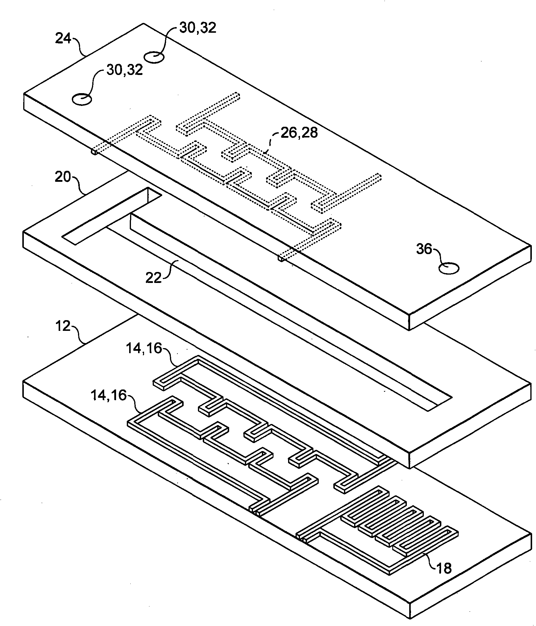
[0149] like figure 1 As shown, the micromixer 10 includes: a base layer 12 formed of glass with three serpentine conductors 14, 16, 18 embedded therein; the middle layer 12 ; and the upper layer 24 formed of glass with two further serpentine conductors 26 , 28 , two inlets 30 , 32 and an outlet 36 embedded therein.

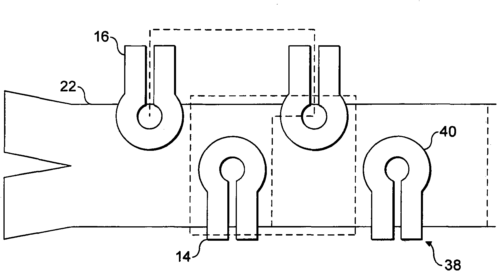
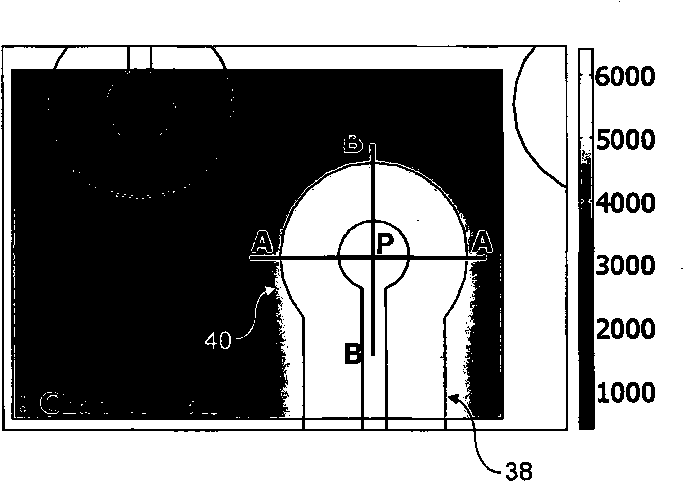
[0150] An example of the size of the device is in the figure 2 is shown in , which illustrates a top view of one mixing cell with boundaries. Each mixing unit includes two adjacent teeth from each conductor. Channel 22 is 150 μm (micrometer) wide and 50 μm deep. The conductors 14, 16 are in the shape of teeth 38 with rounded tips 40 and are 35 μm high and 35 μm wide in cross-section, and the distance between the centers of the rounded tips 40 of the conductors is 100 μm and 65 μm in the x-direction and y-direction respectively . Each row of upper and lower conductors 14, 16 is alternately connected to a power source. The mixing operation cycle consists of ...


PUM


Abstract

A microfluidic device comprising; i) an inlet; ii) a first layer comprising at least first and second current carrying structures, wherein the at least first and second current carrying structures each comprise a plurality of teeth, and wherein the teeth of the first and second current carrying structures are optionally offset such that the teeth of the first current carrying structure are positioned between the teeth of the second current carrying structure; iii) a second layer comprising a first microfluidic chamber in fluid communication with the inlet positioned above the at least first and second current carrying structures of the first layer; and iv) a third layer comprising at least third and fourth current carrying structures wherein the at least third and fourth current carrying structures each comprise a plurality of teeth, and wherein the teeth of the third and fourth current carrying structures are optionally offset such that the teeth of the third current carrying structure are positioned between the teeth of the fourth current carrying structure; and wherein the at least third and fourth current carrying structures are positioned in the third layer so as to be above the first microfluidic chamber and such that the teeth of the third current carrying structure are positioned substantially vertically above or offset from the teeth of the first current carrying structure and the teeth of the fourth current carrying structure are positioned substantially vertically above or offset from the teeth of the second current carrying structure; wherein the teeth have a stem having substantially elliptical tip.

Description

technical field [0001] The present invention relates to microfluidic devices and methods for isolating and detecting analytes from biological samples using the same. Background technique [0002] In the past decade, the emergence of microelectromechanical systems (MEMS), based on the miniaturization of mechanical components and the integration of mechanical components and microelectric systems, has created the potential to fabricate various micron-sized structures and devices. The technology utilizes nearly the same fabrication techniques, equipment and materials as those developed by the semiconductor industry. The range of applications of MEMS has expanded significantly and is mainly in the field of microsensors and microactuators. In recent years, there has been great interest in the miniaturization and integration of biochemical analysis systems with MEMS devices, which has led to the invention of micro-total analysis systems (μ-TAS) and lab-on-a-chip (LOC) systems. ...

Claims


Application Information

Patent Timeline
Patent Type & Authority Applications(China)
IPC IPC(8): B01L3/00B01F13/00
CPCB01L3/502746B01L2400/043B01L3/50273B01L2200/0647B01L3/502761B01L2300/0809B01L2300/0645B01F13/0818B01L2300/087B01F13/0059Y10T436/25B01F33/30B01F33/452G01N27/44791B01F33/3032B01J19/00B01L3/00B01F25/00B01F33/00
Inventor 瓦马德瓦·巴拉钱德兰萨亚德·穆罕迈德·阿齐米杰里米·阿埃伦马苏德·佐尔加尔尼穆罕迈德·礼萨·巴赫曼亚尔普雷德拉格·斯利耶普切维奇
Owner BRUNEL UNIVERSITY
Why Eureka
Try Eureka