
Cylindrical cutter

A cylindrical milling cutter and cutting edge technology, applied in milling cutters, forming cutters, milling machine equipment, etc., can solve problems such as the influence of lateral force on strip running

Inactive Publication Date: 2010-01-20
SMS DEMAG AG
View PDF2 Cites 6 Cited by
  • Summary
  • Abstract
  • Description
  • Claims
  • Application Information

AI Technical Summary

Problems solved by technology

In particular at the strip head and strip end, the guidance on the upper side is not effective before and after the milling cutter, and transverse forces thus also have a negative effect on the strip running

Method used


Image

  • Cylindrical cutter
  • Cylindrical cutter
  • Cylindrical cutter

Examples


Embodiment Construction

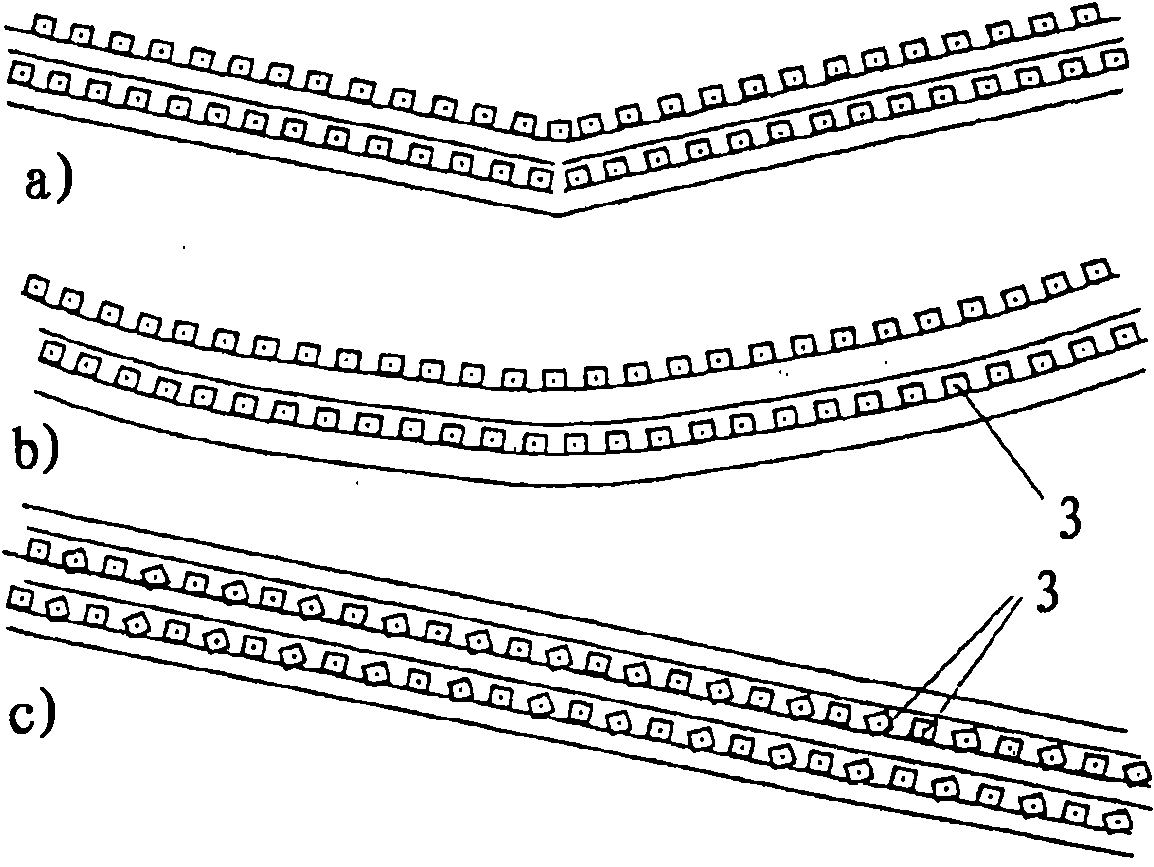
[0030] according to figure 1 In the embodiment shown in , the cylindrical milling cutter comprises a roller body 1, which has a plurality of grooves 2 made in a helical manner on the entire roller circumference for two half-rollers respectively, in which a plurality of indexable inserts are fixed 3. Details which relate neither to fastening nor to roller bearings are not shown, since these are not necessary for understanding here. The cutting edges of the indexable inserts are here arranged or oriented almost in the shape of an arrow. Axial force components are counteracted by a symmetrical arrangement (ie positioning of the cutting edges not only to the left but also to the right), so that the axial forces are minimal (special bead case=0). In the milling machine, the guide for the strip can thus be formed in a simple manner with a small installation space and can be subjected to low loads. Furthermore, in this embodiment the chip splash is directed approximately to the si...


PUM


Abstract

The invention relates to a cylindrical cutter, the roller body of which comprises grooves provided along the length thereof at a distance from one another and at an angle to the longitudinal axis. Indexable inserts, particularly coated hard metal inserts, are disposed in the grooves. In order to largely prevent axial forces from acting on the milling cutter or on the material to be worked, either the grooves and thus the cutting edges of the indexable inserts are aligned sectionally at different angles, said angles being selected such that the axial forces generated in the one section during the milling process are neutralized or are reduced to a defined degree by the axial forces generated in the neighboring section, or the indexable inserts are disposed or aligned alternately in the grooves such that the axial force generated by one indexable insert during the milling process is neutralized by the axial force generated by the neighboring indexable insert.

Description

technical field [0001] The invention relates to a cylindrical milling cutter equipped with a plurality of indexable inserts, in particular coated carbide inserts. Background technique [0002] Cylindrical milling cutters for machining non-ferrous metal strip or sheet metal have been known for a long time. [0003] In DE 2020 4478 U1 a cylindrical milling cutter is described, on which a plurality of helical grooves are formed, in which a plurality of helical inserts (high-speed steel inserts) with almost continuous cutting edges are arranged one after the other, which are secured with wedges and screws fixed. [0004] In order to improve the economy of the milling process, DE 299 131 64 U1, known for example from offset milling cutters, describes the use of cemented carbide indexable inserts for cylindrical milling cutters. Advantageously, it is no longer necessary to fine-grind the blades on a more expensive grinding machine and better utilization is achieved by indexing t...

Claims


Application Information

Patent Timeline
Patent Type & Authority Applications(China)
IPC IPC(8): B23C5/04B27G13/00B27G13/02
CPCB23C2210/045B23C5/04B23C2210/0407B23C2210/0492B23C2210/0428B27G13/04B23C2210/244Y10T407/1902Y10T407/27Y10T407/1934B23C2210/40
Inventor J·塞德尔P·祖道J·默茨M·基平
Owner SMS DEMAG AG
Learn More