
Water scavenging system

A water pipe, water blocking technology, applied in the direction of charging system, engine components, liquid fuel feeder, etc., can solve problems such as failure

Inactive Publication Date: 2010-01-20
AIRBUS OPERATIONS LTD
View PDF2 Cites 4 Cited by
  • Summary
  • Abstract
  • Description
  • Claims
  • Application Information

AI Technical Summary

Problems solved by technology

these components are at risk of failure and communication lines must be pulled out of the fuel tank in a fluid-tight and intrinsically safe manner

Method used


Image

  • Water scavenging system
  • Water scavenging system
  • Water scavenging system

Examples


Embodiment Construction

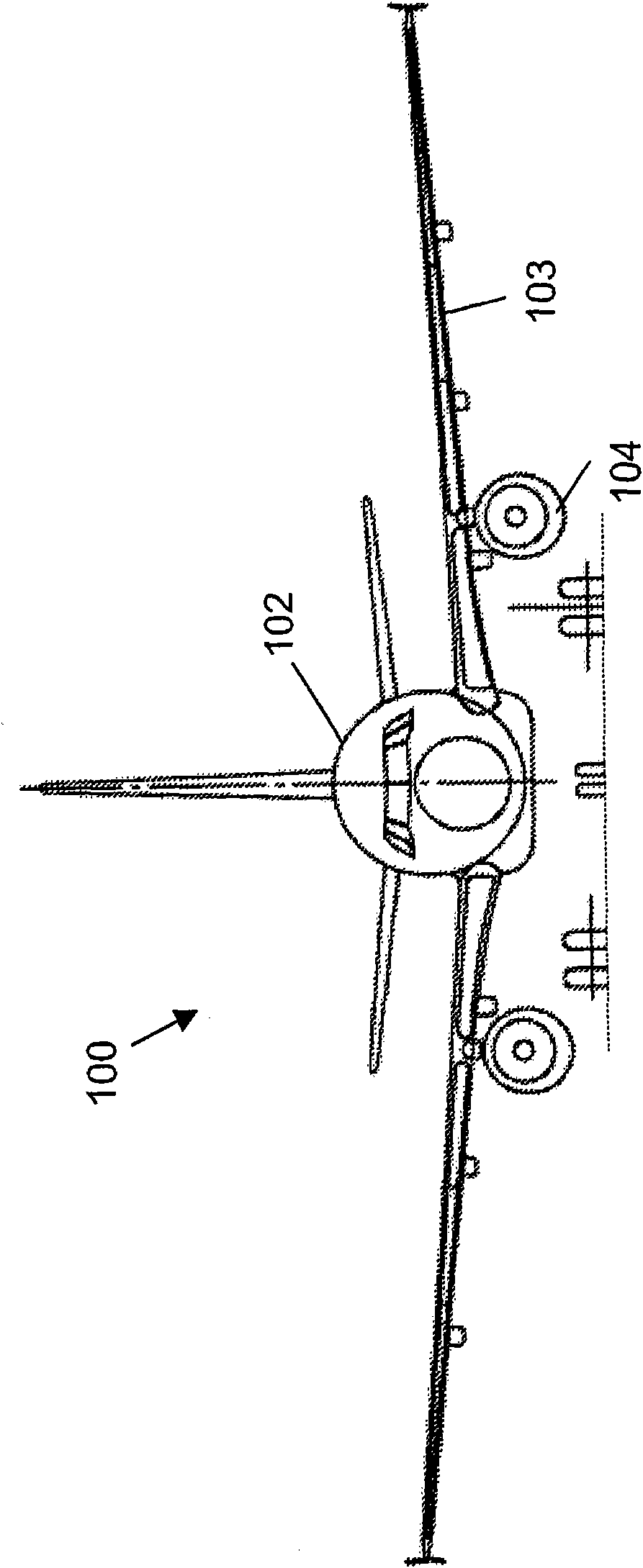
[0023] refer to figure 1 , the aircraft 100 includes a fuselage 102 supporting a pair of wings, the left wing being designated 103 . Each wing carries an engine, figure 1 The engine on the middle left hand side is marked 104. Fuel for each engine is stored in the center tank and one or more wing tanks.

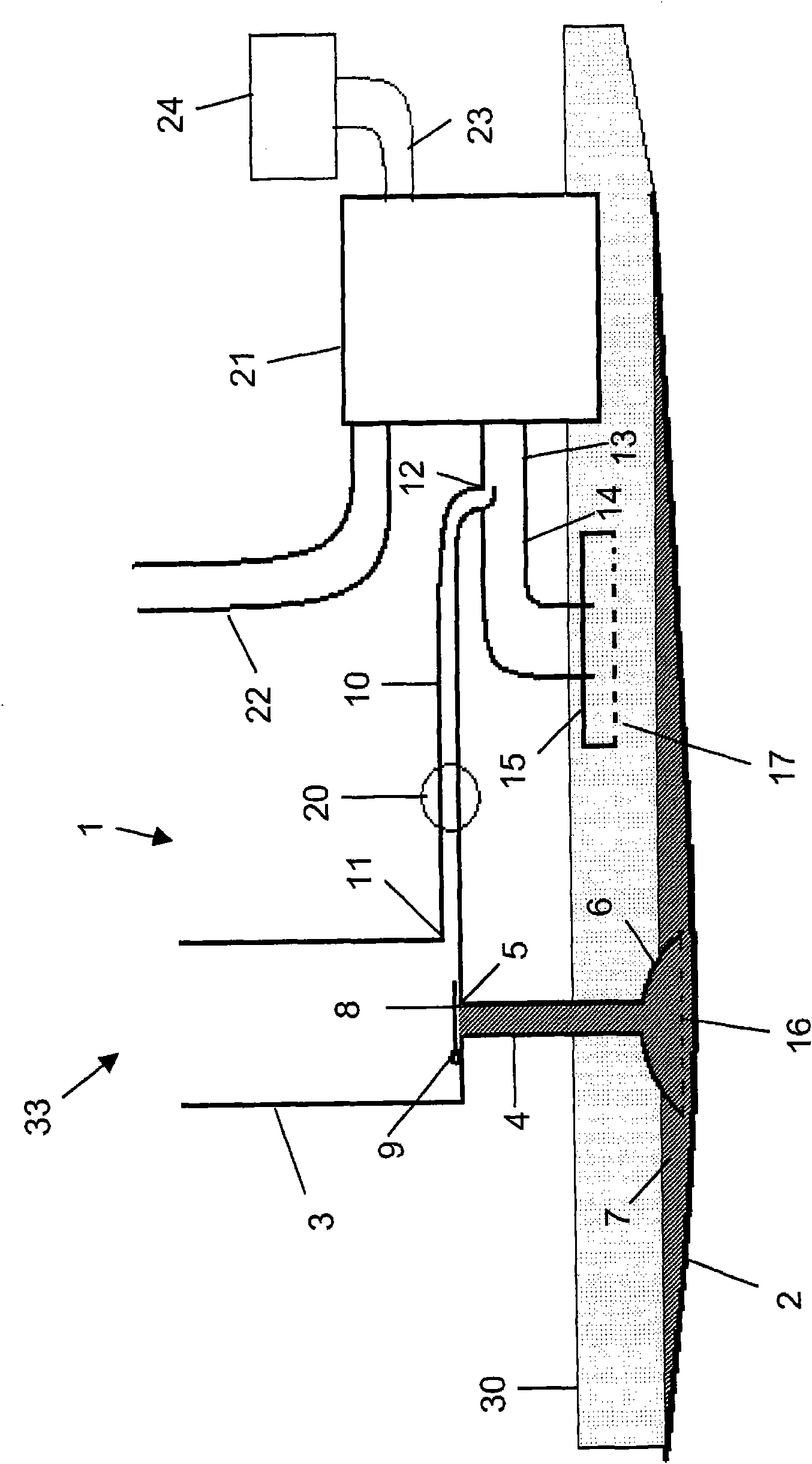
[0024] figure 2 A water removal system is shown in , which is installed in a wing tank 2 . The water removal system comprises a water tank 3 and a water removal pipe 4 having an outlet 5 in the bottom of the water tank 3 and an inlet 6 immersed in pool water 7 at the bottom of the fuel tank 2 . The water tank 3 is usually a vertical pipe with a diameter of 60 mm, a length of 0.4 m and an opening at the top.

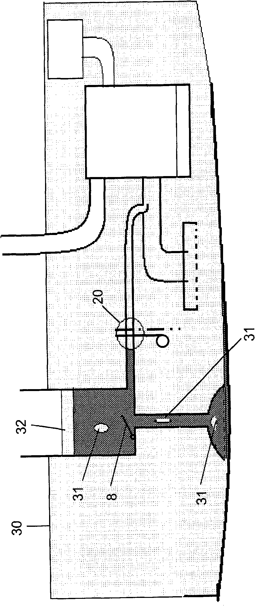
[0025] One-way valve 8 is installed on the water tank, and is installed on the pivot 9, in figure 2 The one-way valve 8 is shown in the closed position, and the one-way valve 8 closes the outlet 5 of the water removal pipe 4 in the closed position. It should be u...


PUM


Abstract

A water scavenging system (1) for removing water from an aircraft fuel tank (2), the water scavenging system comprising: a water line (10); and a valve (20) which is configured to control the flow of water in the water line in response to a change in an effective angle of the valve. In use, the valve opens automatically in response to an increase in the effective pitch of the aircraft during take off and climb. The valve comprises: a pendulum (40); and a valve closure member (46) which is coupled to the pendulum such that a change in the angular position of the pendulum relative to the water line causes the valve closure member to move from a closed position in which the valve closure member impedes the flow of water in the water line to anopen position in which water can flow through the valve.

Description

technical field [0001] The present invention relates to a water removal system. Background technique [0002] A method of removing water from aircraft fuel tanks is described in US4809934. The water removal line collects water dispersed in the fuel just upstream of the booster pump. A first problem with this system is that it requires a complex arrangement of venturis and jet pumps. Another problem is that water can flow into the engine when the engine is running at relatively low speeds. This reduces the operating efficiency of the engine. A further problem is that it is impossible for the system to completely remove water from the fuel tank during a single flight. [0003] A method of removing water from fuel tanks is described in US6170470. Water pipes feed water from the fuel tank into the engine. Since water flowing into the engine when the engine is running at relatively high speeds will not have a significant adverse effect on the operating characteristics of th...

Claims


Application Information

Patent Timeline
Patent Type & Authority Applications(China)
IPC IPC(8): B64D37/14B64D37/22B64D37/34
CPCB64D37/34F02M37/0082Y10T137/0318Y10T137/0753Y10T137/0923
Inventor 安德鲁·明蒂
Owner AIRBUS OPERATIONS LTD
Learn More