
Fluid power transmission device with lockup clutch

A fluid transmission device and lock-up clutch technology, which is applied in fluid transmission devices, transmission devices, clutches, etc., can solve problems such as increasing torque, and achieve the effect of increasing torque and reducing fuel consumption

Inactive Publication Date: 2010-01-20
AISIN AW CO LTD
View PDF1 Cites 12 Cited by
  • Summary
  • Abstract
  • Description
  • Claims
  • Application Information

AI Technical Summary

Problems solved by technology

[0002] Nowadays, automobiles are required to reduce fuel consumption. When looking at the torque converter from the perspective of reducing vehicle fuel consumption, it has the effect of increasing the torque at the start of the vehicle. However, there is still improvement in reducing fuel consumption when driving for a long distance. room for

Method used


Image

  • Fluid power transmission device with lockup clutch
  • Fluid power transmission device with lockup clutch
  • Fluid power transmission device with lockup clutch

Examples


Embodiment Construction

[0052] Embodiments of the present invention will be described below with reference to the drawings. In addition, in the embodiments, the same symbols and the same reference numerals denote parts with the same or equivalent functions, and overlapping descriptions are omitted here.

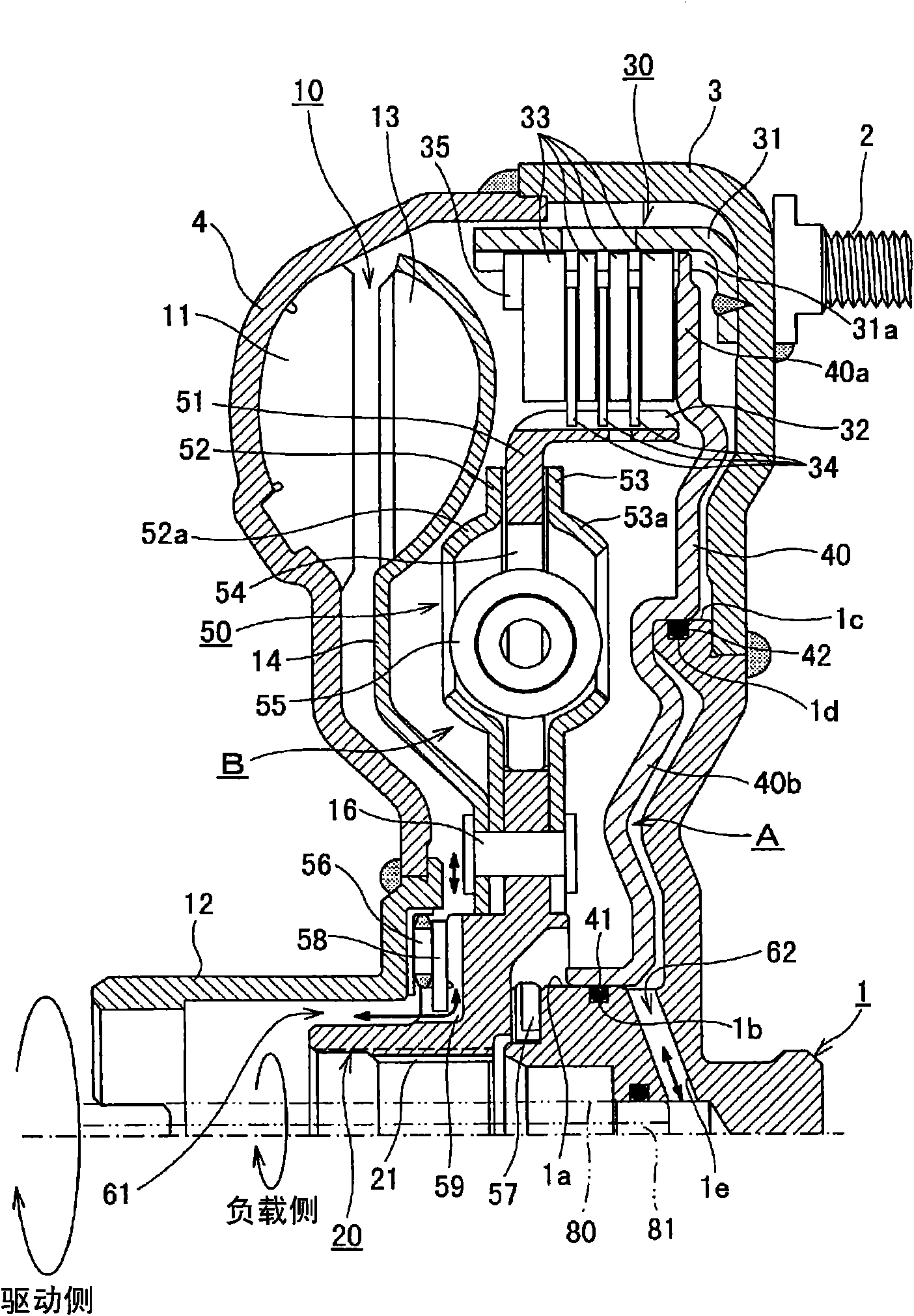
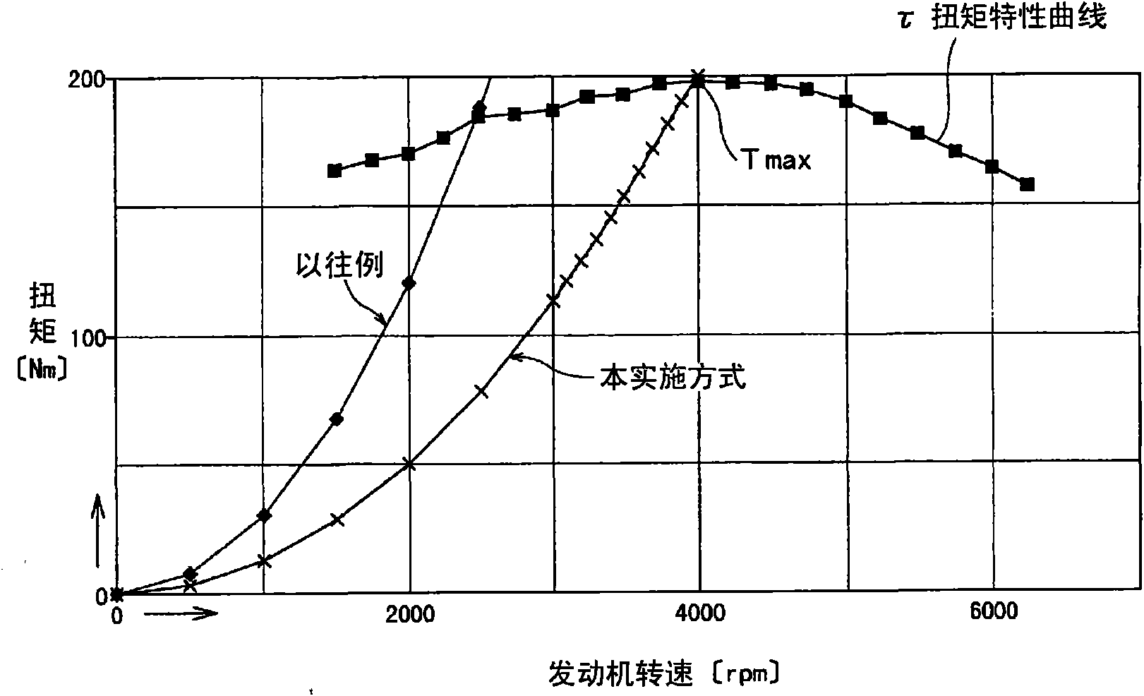
[0053] figure 2 It is a longitudinal sectional view showing a fluid transmission device with a lock-up clutch according to an embodiment of the present invention. image 3 It is a characteristic diagram showing a comparison between the fluid transmission device with a lock-up clutch according to the embodiment of the present invention and the characteristic diagram of a conventional device.

[0054] exist figure 2 Among them, the pin 2 fixed on the front cover 3 and the center member 1 are connected to an internal combustion engine such as a gasoline engine not shown on the driving side. The turbine hub 20 is connected to the speed change mechanism on the load side through splines 21 .

[0055...


PUM


Abstract

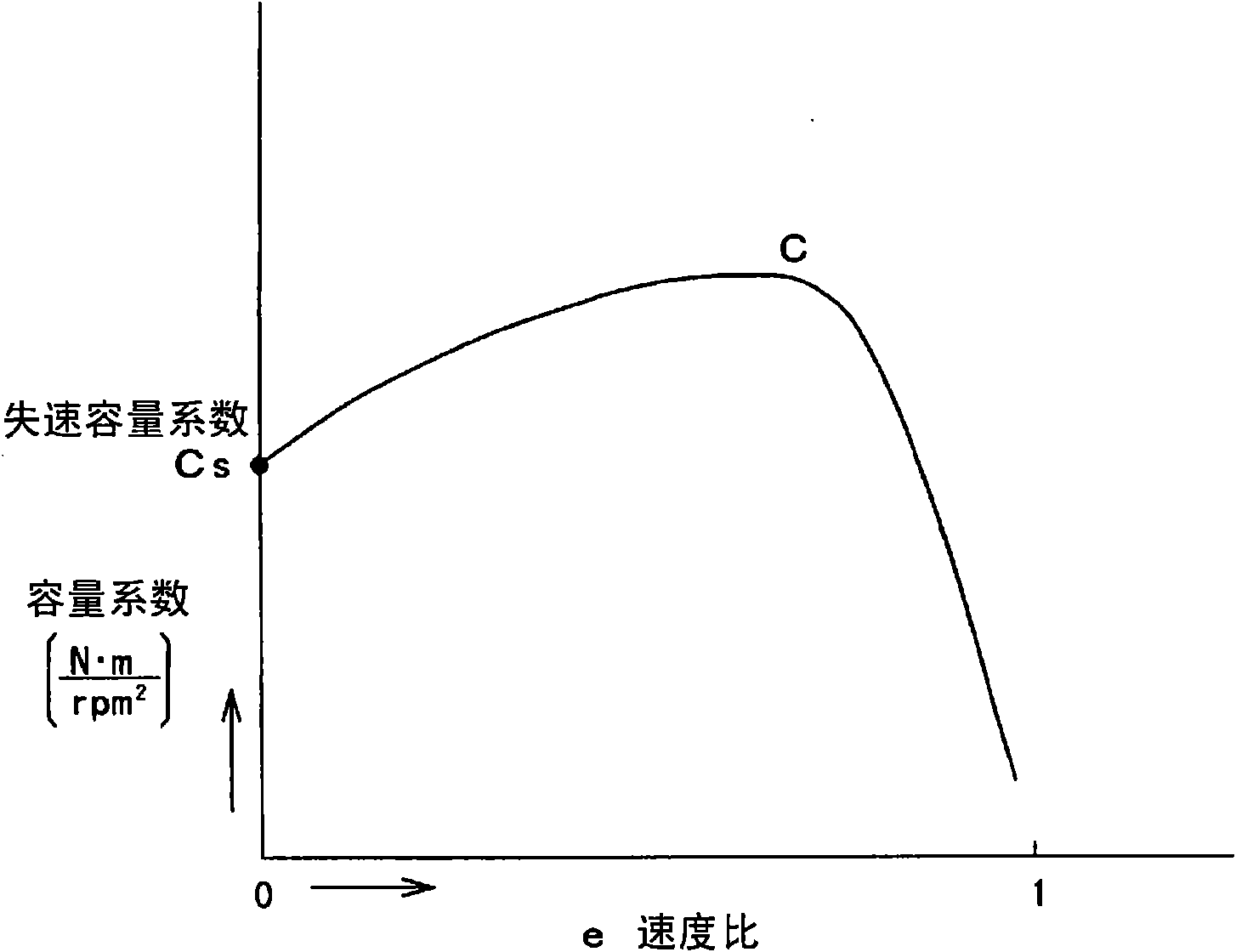
Drivability is improved by generating a maximum engine torque at the time of origination. A lockup clutch (30) for altering a power transmission path is arranged in parallel with the power transmission path between the pump impeller (11) and the turbine runner (13) of a fluid coupling (10) arranged between the drive side and the load side, a stall capacity coefficient Cs¢N m / rpm2! is determined based on an engine r.p.m. generating a maximum engine torque Tmax on the drive side, and used for transmitting rotation on the drive side to the load side. Best accelerability is obtained by setting the stall capacity coefficient Cs such that the stall r.p.m. approaches the r.p.m. for generating a maximum engine torque, drivability is improved by a quantity of control not causing strange feeling between the quantity of stepping an accelerator and the vehicle speed, and the mileage can be enhanced.

Description

technical field [0001] The present invention relates to a fluid transmission device with a lock-up clutch using a fluid joint of an automatic transmission of a vehicle, etc.; more specifically, to a fluid transmission device with a lock-up clutch having a lock-up clutch in the fluid joint . Background technique [0002] Nowadays, automobiles are required to reduce fuel consumption. When looking at the torque converter from the perspective of reducing vehicle fuel consumption, it has the effect of increasing the torque at the start of the vehicle. However, there is still improvement in reducing fuel consumption when driving for a long distance. room for. [0003] Therefore, there is a technology disclosed in Patent Document 1 as a conventional fluid transmission device with a lock-up clutch. Patent Document 1 discloses the following technology, that is, the fluid joint device (1) has: an integral housing (3, 4) connected to the output shaft of the engine (in addition, the n...

Claims


Application Information

Patent Timeline
Patent Type & Authority Applications(China)
IPC IPC(8): F16D47/06F16H45/02
CPCF16D25/0638F16D2500/7044F16D33/00F16H2045/0284F16D47/06F16D2500/30406F16H2045/021F16D2500/3067F16D48/066F16H2045/0247F16D2500/1026F16D2500/5048F16D2500/3065
Inventor 阿部唯人荒木敬造伊藤一能铃木明智石川和典
Owner AISIN AW CO LTD
Learn More