Ice-storage low-temperature pipe type air supply device

An air supply device and pipeline-type technology, which is applied in the field of pipeline-type air supply devices, can solve the problems of strong cold wind, low air supply temperature, power consumption, etc., and achieve the effect of simple manufacture, small space occupation and no cost

Inactive Publication Date: 2010-01-27
UNIV OF SHANGHAI FOR SCI & TECH
View PDF0 Cites 2 Cited by
  • Summary
  • Abstract
  • Description
  • Claims
  • Application Information

AI Technical Summary

Problems solved by technology

[0004] The main problem of the low-temperature air supply system currently used at home and abroad is that the temperature of the air supply is too low, and it is easy to cause condensation at the air outlet when it is directly sent into the room, and produce a strong sense of cold wind; most of the existing induction boxes use fans as power , resulting in a certain amount of power consumption

Method used


Image

  • Ice-storage low-temperature pipe type air supply device
  • Ice-storage low-temperature pipe type air supply device
  • Ice-storage low-temperature pipe type air supply device

Examples


Embodiment 1

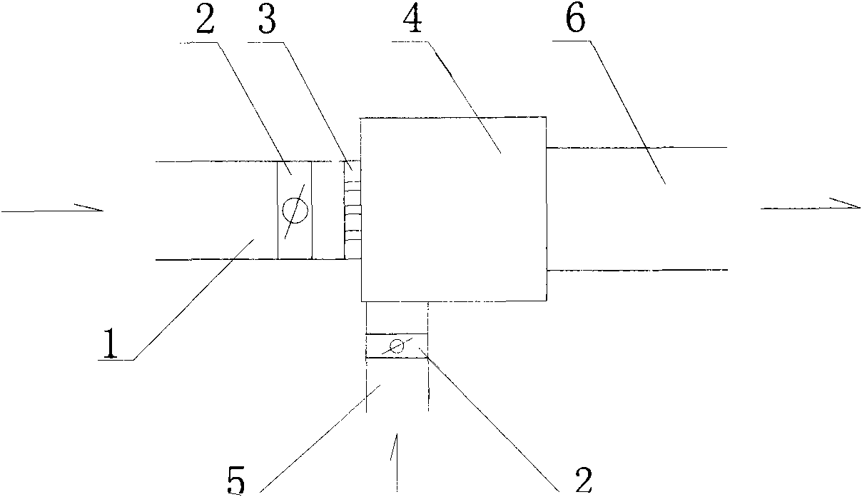
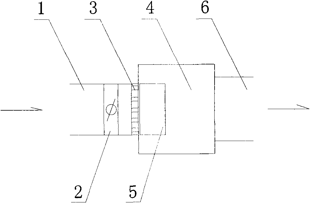
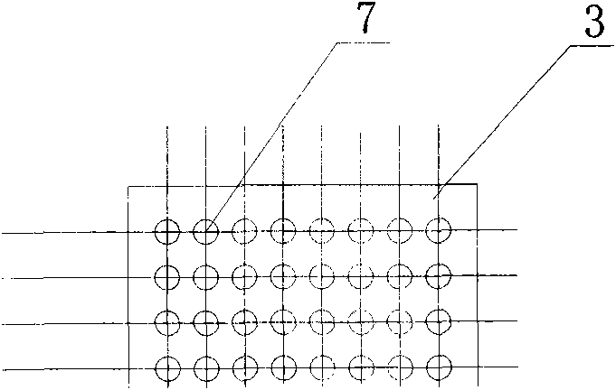
[0017] An ice-storage low-temperature pipeline air supply device, such as figure 1 shown. The primary air inlet pipe 1 is connected with a damper 2, the end of the primary air inlet pipe 1 is connected to the induced mixing box 4, the induced mixing box 4 is connected to the mixed air outlet pipe 6, and the primary air inlet pipe 1 is installed with An induction orifice 3, the side wall of the induction mixing box is provided with an induction tuyere, the induction air outlet is connected to the induction air duct 5, and the induction air duct is provided with a damper 2, and the arrangement of the holes 7 of the induction orifice is as follows: image 3 As shown, the holes are the same size and evenly distributed. In this embodiment, the induced tuyere is arranged at the bottom of the induced mixing box 1, such as figure 2 As shown, the position is close to the induction orifice plate 3. The ratio of the area of ​​the induction orifice 3 to the cross-sectional area of ​​t...

Embodiment 2

[0020] The difference from Example 1 is that there are two induced tuyeres in this embodiment, one is set at the bottom of the induced mixing box 1, and the other is set at the side wall of the induced mixing box 1 parallel to the air supply direction. The ratio of the area of ​​the induction orifice 3 to the cross-sectional area of ​​the primary air inlet duct 1 is 2:3. It satisfies the requirement of inducting indoor air into the induction mixing box, and after being mixed in the box, the mixed air at a suitable temperature is sent out from the mixed air outlet pipe 6, and the air-conditioning air enters the air supply port of the room without condensation and dripping.

Embodiment 3

[0022] The difference from Embodiment 1 and Embodiment 2 is that in this embodiment, there are two induced tuyeres, which are respectively arranged on the two side walls of the induced mixing box 1 parallel to the air supply direction. The ratio of the area of ​​the induction orifice 3 to the cross-sectional area of ​​the primary air inlet duct 1 is 1:2. It satisfies the requirement of inducting indoor air into the induction mixing box, and after being mixed in the box, the mixed air at a suitable temperature is sent out from the mixed air outlet pipe 6, and the air-conditioning air enters the air supply port of the room without condensation and dripping.


PUM


Abstract

The invention discloses an ice-storage low-temperature pipe air supply device. The tail end of a primary air inlet pipe is connected with an induction mixing box, the induction mixing box is connected with a mixed air outlet pipe, an induction pore plate is arranged in the primary air inlet pipe, an induction air port is arranged on the wall of the induction mixing box, the induction air port is connected with the induction air pipe, and the induction air pipe is equipped with an air valve therein. Pores of the induction pore plates are same and evenly distributed; and ratio of area of the induction pore plate to the sectional area of the primary air inlet pipe is 1:3-2:3. The ice-storage low-temperature pipe air supply device can supply air with proper temperature to rooms, and produce no dew and dripping when sending conditioned air to an air inlet. The device has the advantages of flexible and convenient arrangement, simple production, small occupied space, no additional power supply and low cost.

Description

technical field [0001] The invention relates to a low-temperature air-supply central air-conditioning system combined with ice storage, with a pipeline-type air-supply device for adjusting air volume. Background technique [0002] The low-temperature air supply was first proposed in 1947, and it was initially only used in the renovation project of ordinary central air-conditioning systems. In 1983, the U.S. Department of Energy formally proposed at the International Conference on "Application of Cold Storage in Air-Conditioning Engineering" that low-temperature air supply can further exert the advantages of ice-storage air-conditioning systems, and can compete with non-ice-storage systems in terms of initial investment. The low-temperature air-supply central air-conditioning system was applied in commercial buildings in the United States in the mid-1980s. [0003] Since the proportion of building energy consumption in the total energy consumption of society is increasing ye...

Claims


Application Information

Patent Timeline
Patent Type & Authority Applications(China)
IPC IPC(8): F24F13/04
Inventor 王瑾周尤涛王素英王刚唐昌亮
Owner UNIV OF SHANGHAI FOR SCI & TECH
Why Eureka
Try Eureka