Main spindle retraction mechanism

A technology of spindle and tool retraction, applied in the directions of metal processing machinery parts, clamping, support, etc., can solve the problems of difficult machine tool coordination and assembly, structural difficulties, increased cost, etc., to achieve convenient and flexible device layout, maintain accuracy, and facilitate assembly and maintenance. Effect

Active Publication Date: 2009-05-27
南通西马特机械制造有限公司
View PDF0 Cites 4 Cited by
  • Summary
  • Abstract
  • Description
  • Claims
  • Application Information

AI Technical Summary

Problems solved by technology

[0002] The tool retracting action of the machine tool spindle is a key point involving production efficiency, safe operation, labor intensity and maintaining the accuracy of the spindle. After the advent of CNC machine tools, the tool retracting technology has been well resolved, but the retracting tool of the drilling machine or drilling and milling machine has been used. The actions of hand knocking, hand board, and hand punching have been tackled in the drilling machine industry as early as the 1980s. So far, there have been various mechanisms and methods of tool retraction, but they are all manual actions and have many defects.
There are two reasons why the automatic broaching and retracting technology of drilling machine or drilling and milling machine is difficult to solve. The first is technical aspect. In the key sleeve, this requires that the diameter of the retracting cylinder assembly must be smaller than the diameter of the spindle spline, and must adapt to the two combined movements of the spindle, which is already very difficult in structure. In addition, the retracting cylinder is very small, reaching more than 1000kgf The tool withdrawal force must have high-pressure oil above 10Mpa, while the pressure of conventional gear oil pumps is only 2.5Mpa, which is impossible for drilling machines or drilling and milling machines; secondly, drilling machines or drilling and milling machines are ordinary machine tools, although automatic broaching is very necessary. But it is impossible to greatly increase the cost to improve this function. For example, in order to provide high-pressure oil source, it is necessary to configure high-pressure oil cylinder, high-power motor (its power may be greater than the main motor of the machine tool) and hydraulic system, which is not only expensive but also the volume of the device Very large, difficult to coordinate and assemble with the machine tool as a whole

Method used


Image

  • Main spindle retraction mechanism
  • Main spindle retraction mechanism
  • Main spindle retraction mechanism

Examples


Embodiment Construction

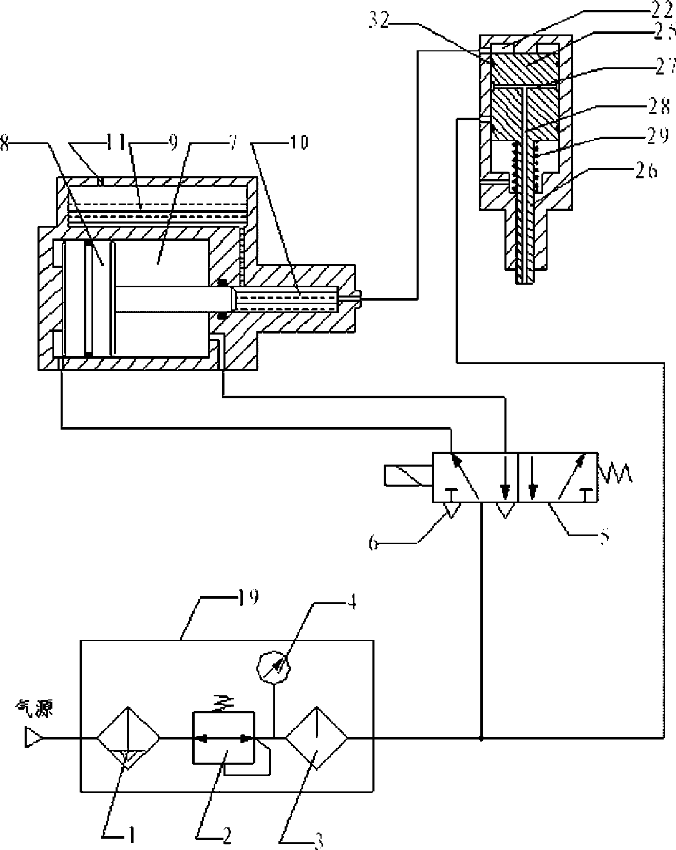
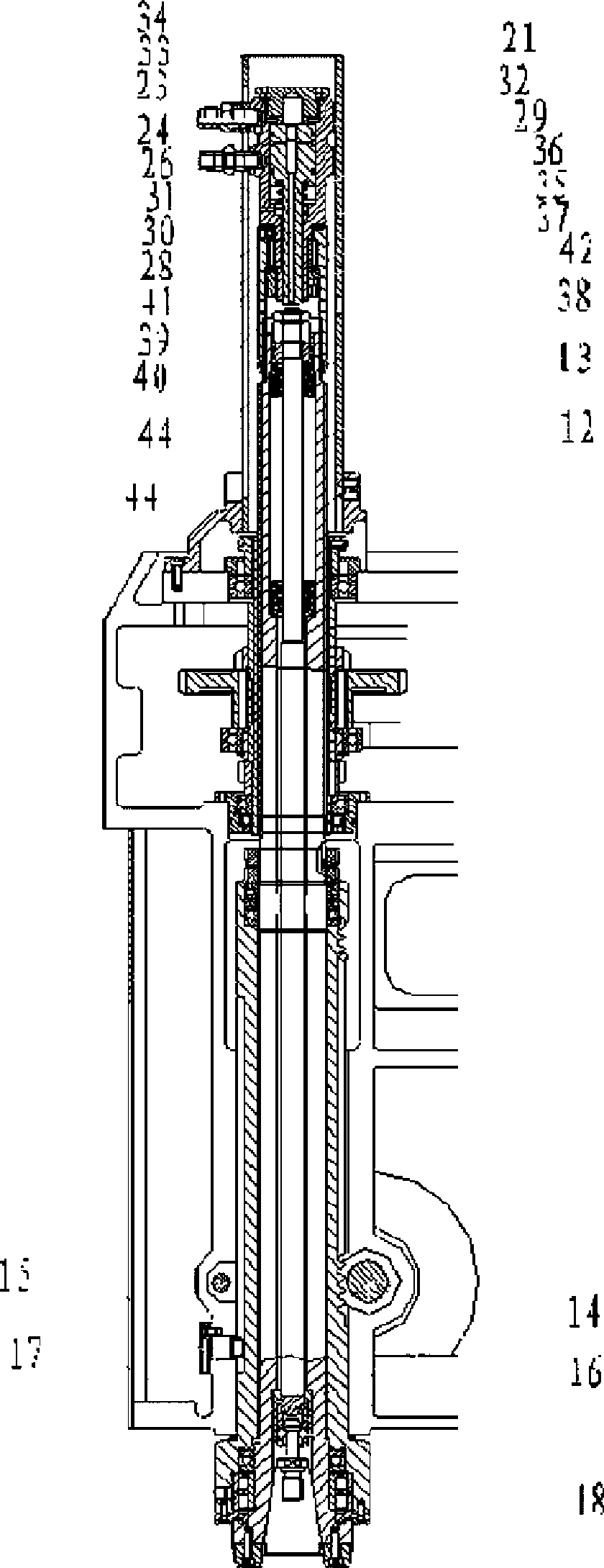
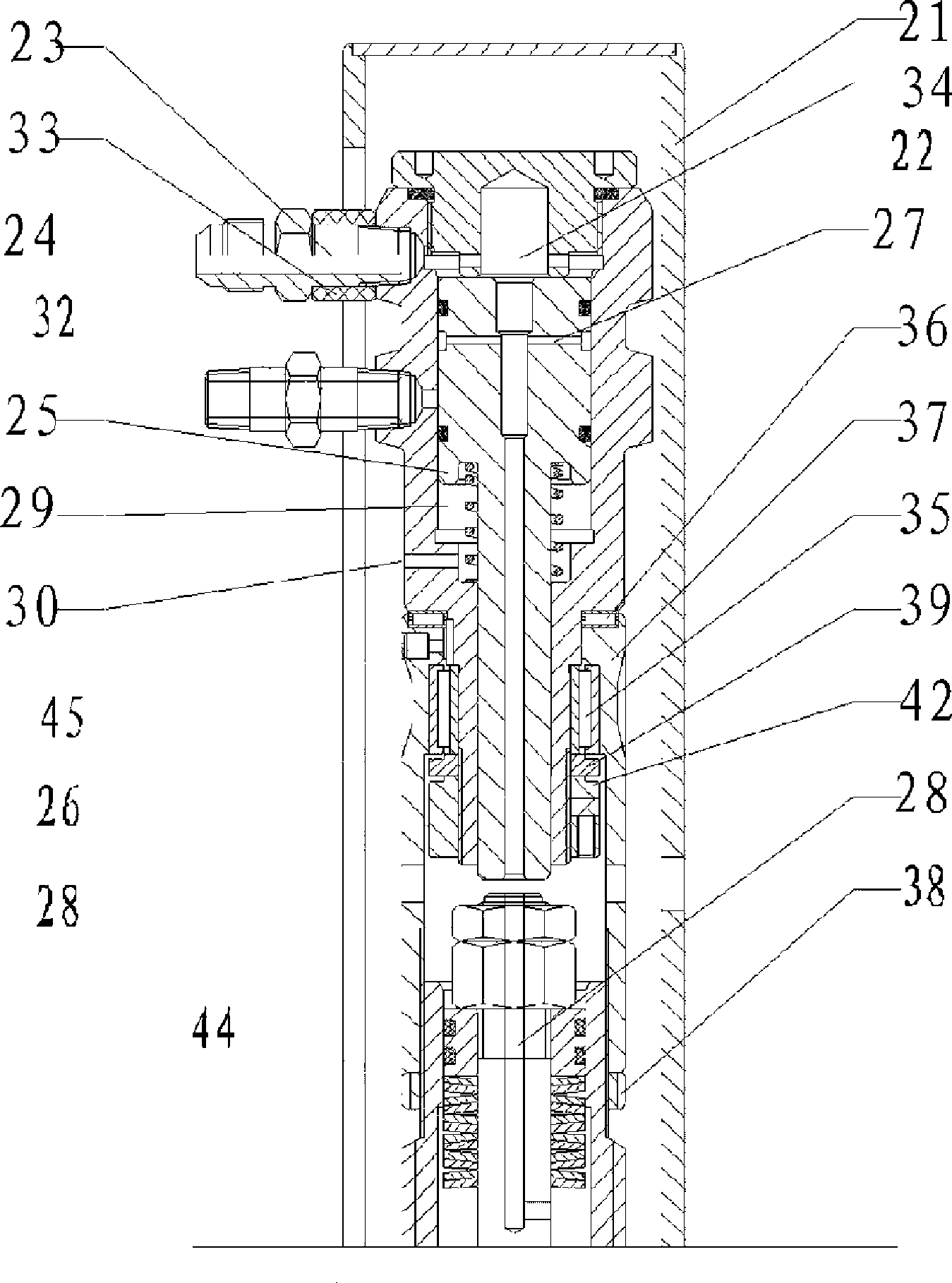
[0033] Such as Figure 1-5 As shown, the main shaft retracting mechanism of the present invention includes a gas-hydraulic retracting power system, a retracting assembly and a knife rod 12, and the gas-hydraulic retracting power system includes a pneumatic triple piece 19, a two-position five-way solenoid valve 5 and a gas-liquid booster Device 20, a muffler 6 is provided on the two-position five-way electromagnetic valve 5, the tool bar 12 is sleeved in the main shaft 13, two butterfly springs 44 are arranged between the tool bar 12 and the main shaft 13, and the lower end of the tool bar 12 is a conical head shape, the conical head 14 has an inclined air hole 15, the lower end of the knife rod 12 is covered with a sleeve 16, the head of the pull rivet 17 is placed in the sleeve 16, and there are 5 evenly distributed along the neck of the pull rivet 17 in the sleeve 16. The steel ball 18 and the tool retraction assembly include a high-pressure oil cylinder 22 covered with a p...


PUM


Abstract

The invention relates to a mainshaft cutter withdrawal mechanism which is characterized in that an air-hydraulic withdrawal power system comprises an air-hydraulic booster; a cutter withdrawal component comprises a high-pressure oil cylinder which is covered by a protection cover; one side of the high-pressure oil cylinder is provided with an oil pipe joint; the high-pressure oil cylinder at the lower side of the oil pipe joint is provided with an air pipe joint; the high-pressure oil cylinder is internally provided with a piston; the lower end of a piston rod of the piston and the upper end of a cutter arbor are provided with a certain distance; the piston is internally provided with a transverse perforated air passage and a longitudinal air passage which is communicated with the transverse air passage; the opening of the longitudinal air passage is arranged at the lower end of the piston rod; a section of piston rod between the piston and the bottom of the high-pressure oil cylinder is sheathed by a spring; the side wall of the bottom of the high-pressure oil cylinder is provided with an exhaust hole; the upper part of the cutter arbor is also provided with a section of longitudinal air passage with openings at the top; the lateral opening of the lower end of the longitudinal air passage is arranged between the cutter arbor and the mainshaft. In the invention, the mainshaft cutter withdrawal mechanism has the advantages of small volume, light weight, convenient and flexible layout, no influence on the appearance of the machine tool, convenient assembly and maintenance and low manufacturing cost.

Description

technical field [0001] The invention relates to drilling machines and drilling and milling machine equipment, in particular to one of the main shaft retracting mechanisms. Background technique [0002] The tool retracting action of the machine tool spindle is a key point involving production efficiency, safe operation, labor intensity and maintaining the accuracy of the spindle. After the advent of CNC machine tools, the tool retracting technology has been well resolved, but the retracting tool of the drilling machine or drilling and milling machine has been used. The actions of hand knocking, hand board, and hand punching have been tackled in the drilling machine industry as early as the 1980s. So far, there have been various mechanisms and methods of tool retraction, but they are all manual actions and have many defects. There are two reasons why the automatic broaching and retracting technology of drilling machine or drilling and milling machine is difficult to solve. The...

Claims


Application Information

Patent Timeline
Patent Type & Authority Applications(China)
IPC IPC(8): B23Q3/157
Inventor 王豫康龚建浩何发辉
Owner 南通西马特机械制造有限公司
Why Eureka
Try Eureka