
Open experiment device for teaching local resistance measurement during air flowing

An experimental device and air flow technology, applied in measuring devices, teaching models, measuring fluid pressure, etc., to reduce power, reduce local resistance, cultivate professional knowledge and scientific research and innovation capabilities

Inactive Publication Date: 2010-01-27
HARBIN INST OF TECH
View PDF0 Cites 5 Cited by
  • Summary
  • Abstract
  • Description
  • Claims
  • Application Information

AI Technical Summary

Problems solved by technology

The prior art fails to provide an experimental device for measuring the relationship between the flow resistance and the various changes of the flow velocity and the flow path during the air flow process

Method used


Image

  • Open experiment device for teaching local resistance measurement during air flowing
  • Open experiment device for teaching local resistance measurement during air flowing
  • Open experiment device for teaching local resistance measurement during air flowing

Examples


specific Embodiment approach 1

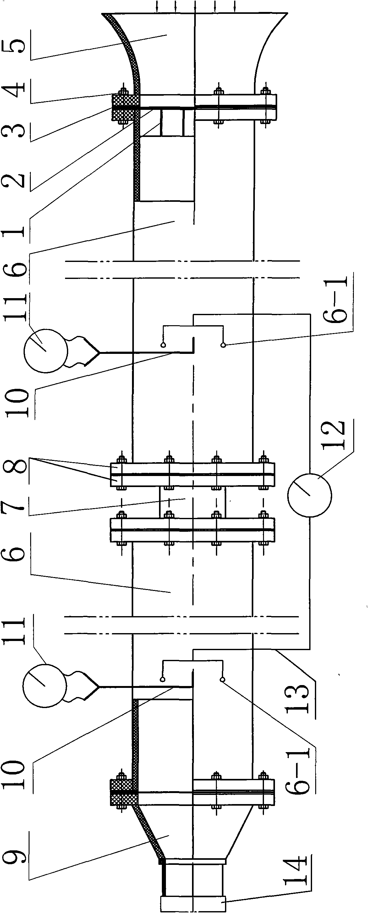
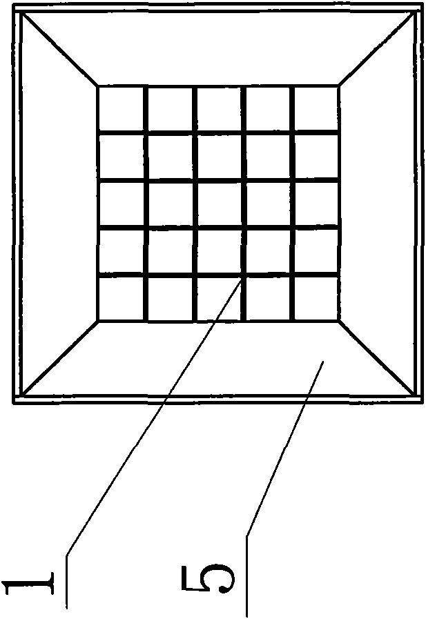
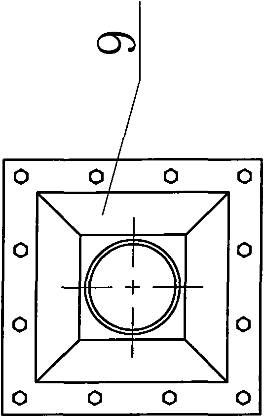
[0007] Specific implementation mode one: as Figure 1~3 As shown, an open air flow local resistance measurement teaching experiment device described in this embodiment includes a variable frequency speed regulation induced draft fan 14, a contraction section pipe 9, two measurement section pipes 6, an experimental section 7, an air inlet section pipe 5, Two Pitot tubes 10, two electronic micromanometers 11, two groups of pipelines 13 and an electronic micromanometer 12 for measuring differential pressure; the variable frequency speed regulation induced draft fan 14 communicates with the small end of the constriction pipe 9, The test section 7 is arranged between the two measuring section pipes 6 and is detachably communicated with respective one ends of the two, the large end of the constricting section pipe 9 communicates with the other end of one of the two measuring section pipes 6, and the two The other end of another in the measuring section pipe 6 communicates with an en...

specific Embodiment approach 2

[0009] Specific implementation mode two: as Figure 4~6 As shown, the experimental section 7 in this embodiment is a cylinder with a square cross-section and tapered or a quadrangular cylinder with a shrinking cross-section. Other components and connections are the same as those in the first embodiment.

specific Embodiment approach 3

[0010] Specific implementation mode three: as Figure 7-8 As shown, the experimental section 7 in this embodiment is composed of two cylinders 7-2 with a square cross-section and tapered, and the small ends of the two cylinders 7-2 with a square cross-section and tapered connected together. Other components and connections are the same as those in the first embodiment.


PUM


Abstract

An open experiment device for teaching the local resistance measurement during air flowing relates to an experiment device for measuring the local resistance during the air flowing. The open experiment device aims at measuring the change of local flowing resistance in the flowing process, which happens together with the change of a flow passage and the change of flowing speed, so as to further obtain a flow passage structure with the minimum flowing resistance in the same wind speed. A frequency-variable speed-regulating draught fan is communicated with a small end of a retraction section tube. An experiment section is arranged between two measurement section tubes and detachably communicated with one end of each of the two measurement section tubes. Each measurement section tube is provided with a Pitot tube. Each Pitot tube is connected with an electronic microtasimeter. The middle part of the lateral wall of each measurement section tube is provided with at least two pressure obtaining holes. The pressure obtaining holes on the two measurement section tubes are respectively communicated with pipelines and connected with the electronic microtasimeters for measuring pressure difference. Due to the open experiment device, the flow passage structure with the minimum flowing resistance in the same wind speed can be obtained. The resistance in the flowing process is reduced so that the power of the fan for driving the flow is greatly lowered, the electricity consumption is reduced, and the energy is saved.

Description

technical field [0001] The invention relates to an experimental device for measuring air flow local resistance. Background technique [0002] Gas transportation using air as the medium widely exists in production and life, and the transportation process consumes energy to overcome the resistance of the flow process. Drag reduction technology is of great significance to saving energy, reducing noise, and protecting the ecological environment. The resistance generated in the process of fluid transportation is divided into along-way resistance and local resistance. It is difficult to reduce the along-way resistance, but most of the local resistance can be reduced by taking drag-reducing measures. Sudden changes in the shape and geometric dimensions of the flow channel during fluid transportation will cause fluid disturbances and change the original flow state. Typical working conditions such as sudden contraction, sudden expansion, turning, fluid diversion and flow are common ...

Claims


Application Information

Patent Timeline
IPC IPC(8): G09B23/12G01P5/16G01L9/00
Inventor 姜宝成田灵智刘晓波黄怡珉王洪杰
Owner HARBIN INST OF TECH
Learn More