Prone type cervical correcting device

A correction device, prone technology, applied in the fields of medical science, fractures, passive exercise equipment, etc., can solve the problems of the patient's head being restrained, the effect is not good, and it is difficult to self-adjust, so as to relieve neck and neck muscle spasm, Enhance the effect of treatment, the effect of high applicability

Inactive Publication Date: 2010-02-03
欧阳刚
2 Cites 9 Cited by

AI-Extracted Technical Summary

Problems solved by technology

[0002] At present, the known cervical traction devices all have to pull the head by external force to produce cervical traction effect. This type of cervical traction devices has the following disadvantages: 1. The patient's head is in a restrained state during the traction process, and it is difficult to self-adjust
2. The effective traction of the cervical spine by the tractor needs to overcome the weight of the head itself. The traction headgear exerts a large force on the headrest and mandible (the strength of the seat tractor is more than 5 kg), and long-term use may ...

Abstract

The invention discloses a prone type cervical correcting device which comprises a base, two chest shoulder pads, a chin pad and a forehead pad. The two chest shoulder pads are symmetrically arranged on the base; the two chest shoulder pads, the chin pad and the forehead pad are supported on the base by a chest shoulder pad supporting frame, a chin pad supporting device and a forehead pad supporting device, wherein the chin pad supporting device comprises a rear supporting strip and a front supporting strip; the front supporting strip and the rear supporting strip are articulated with each other; one end of the rear supporting strip is articulated on the base; the other end of the front supporting strip is movably supported in a supporting groove on the base; the supporting groove is formedby a plurality of small grooves arranged in parallel and in a shape matched with the shape of the end of the front supporting strip; the lower end of the chin pad is articulated at the articulated end of the front supporting strip and the rear supporting strip; the chin pad is a concave supporting pad matched with the shape of a human chin; and the forehead pad supporting device comprises a forehead supporting base and a height adjusting mechanism arranged above the forehead supporting base. The invention has the advantages of appropriate force application, comfortable use and good treatmenteffect.

Application Domain

Technology Topic

Treatment effectForehead +4

Image

  • Prone type cervical correcting device
  • Prone type cervical correcting device
  • Prone type cervical correcting device

Examples

  • Experimental program(1)

Example Embodiment

[0019] The present invention will be further described in detail below in conjunction with the drawings and specific embodiments.
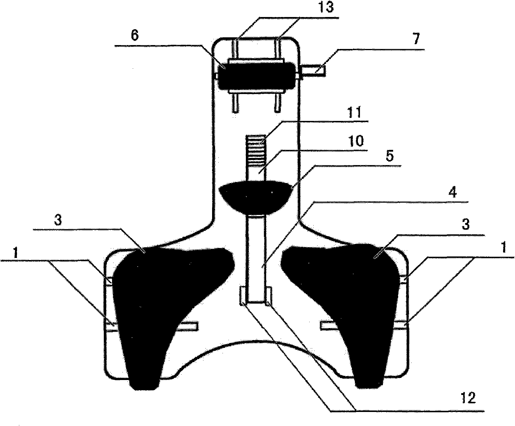
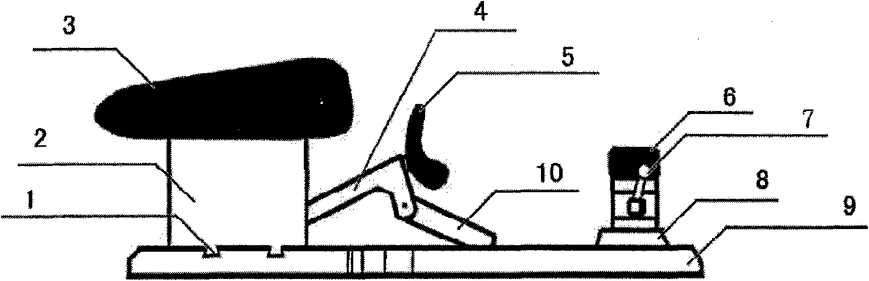
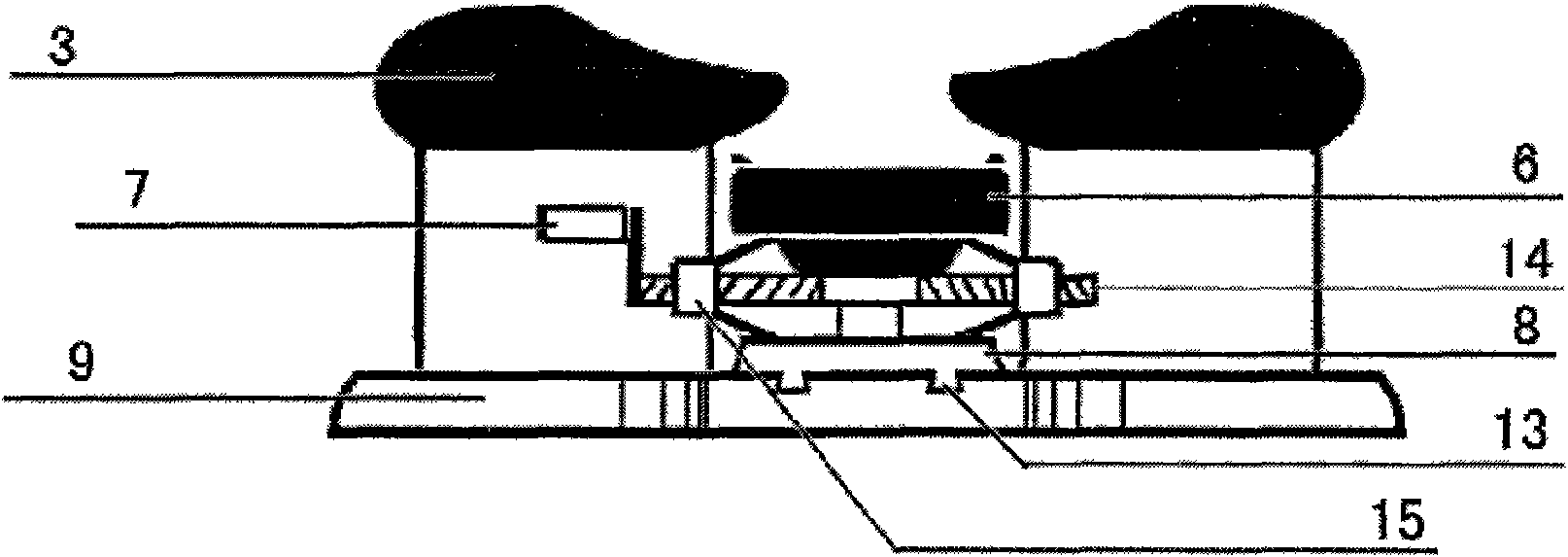
[0020] In specific implementation, such as Figure 1 to Figure 4 As shown, a prone cervical spine correction device has a structure including a base 9, two chest and shoulder pads 3, a chin pad 5 and a forehead pad 6 symmetrically arranged on the base 9, the chest and shoulder pads 3, and chin pads 5. The positions of the forehead pad 6 correspond to the positions of the left and right chest, shoulders, chin, and forehead when a person is lying prone on the base, and are supported on the base 9 by the chest and shoulder pad support frame 2, chin pad support device and forehead pad support device. Wherein, the base 9 corresponding to the two chest and shoulder pad support frames 2 is provided with a dovetail groove 1 transversely, and the bottom of the two chest and shoulder pad support frames 2 are respectively provided with protruding parts matching the dovetail groove 1 to slidably catch Connected in the dovetail groove 1; the chin cushion support device includes a rear support bar 4 and a front support bar 10. One end of the rear support bar 4 is hinged on the support plate 12 on the base 9, and the other end is connected to the front support bar One end of the front support bar 10 is hinged, and the other end of the front support bar 10 is movably supported in the support groove 11 on the base 9. The support groove 11 is composed of a plurality of parallelly arranged small grooves matching the contour at the end of the front support bar 10 The lower end of the chin pad 5 is hinged at the ends of the front and rear support bars 10 and 4, and the upper surface of the chin pad 5 has an arc-shaped tip that matches the shape of the human chin; the forehead pad support device includes a A forehead support base 8 and a height adjustment mechanism arranged above the forehead support base 8. The base 9 below the forehead support base 8 is provided with a dovetail groove 13 along the direction of the chin pad 5. Below the forehead support base 8 A protruding part matching the dovetail groove 13 is slidably clamped in the dovetail groove 13. In specific implementation, the height adjustment mechanism is structured as follows: a horizontally arranged rotating shaft 14 is provided with symmetrically distributed threads at both ends of the rotating shaft 14, and two rotating sleeves 15 are respectively screwed on the threads. The upper and lower ends of 15 are respectively hinged with a support rod, and the other ends of the four support rods are hinged on the forehead support base 8 and the forehead pad 6 respectively in pairs, and one end of the rotating shaft 14 is also provided with A turn handle 7. In addition, during specific implementation, the upper surface shapes of the chest and shoulder pads 3, chin pads 5, and forehead pads 6 respectively match the contours of the chest and shoulders, chin, and forehead when a person is prone on them. Specifically, the upper surface of the chin pad 5 can be made into a concave arc shape adapted to the chin of the human body, and the upper end of the arc shape can also be set in a concave arc shape adapted to the neck and neck of the human body in the transverse direction; the chest and shoulder pad 3 The above table can be set to match the body's chest and shoulders. The shoulder support pad has a certain height to make the body's chest hang in the air. It will not affect breathing or compress the chest when used, and it will also help the user to stretch and expand the chest. 、Relax or exercise the back muscles; the upper surface of the forehead pad 6 can be directly set as a plane structure.
[0021] When it is used, such as Figure 5 As shown, the user is lying prone on the present invention and supported by the chest and shoulder pads and chin pad. The chin pad changes the reaction force of about 1/2 of the user's head gravity into a pulling force along the top of the user's head. The direction of force is basically parallel to the direction of the human cervical spine; at the same time, the cervical spine tension and bending angle are changed by adjusting the height and position of the forehead pad to correct different cervical spine lesions. At the same time adjust the height and position of the forehead pad, the angle and height position of the chin pad, and the left and right positions of the chest and shoulder pads so that it can be well adapted to different users. In specific implementation, the prone cervical spine stretcher seat frame, shoulder support cushion support, mandibular support cushion support, and forehead support cushion support are made of engineering plastics, shoulder support pads, chin support pads, forehead support pads and other human bodies The contact part is made of flexible foam artificial leather and is ergonomically designed. The patient will naturally relax and feel comfortable during use.
[0022] The scope of protection of the present invention is not limited to this specific embodiment, and various changes can be made within the scope of protection outlined in claim 1 of the present invention. For example, the height adjustment mechanism can also be set to other structural forms; the dovetail The groove structure can also be replaced with other structures or not provided; the shape and material of the chest and shoulder pads, chin pads, and forehead pads can also be changed in other ways; the above-mentioned changes should still be regarded as still falling within the protection scope of the present invention .

PUM

no PUM

Description & Claims & Application Information

We can also present the details of the Description, Claims and Application information to help users get a comprehensive understanding of the technical details of the patent, such as background art, summary of invention, brief description of drawings, description of embodiments, and other original content. On the other hand, users can also determine the specific scope of protection of the technology through the list of claims; as well as understand the changes in the life cycle of the technology with the presentation of the patent timeline. Login to view more.

Similar technology patents

Method for eliminating vignetting phenomenon in surgical microimaging

PendingCN111260573AGood correction effectEliminate vignettingImage enhancementOphthalmologyMicrosurgery
Owner:ZHEJIANG FUTURE TECH INST JIAXING

Construction method for deviation rectification of open caisson

PendingCN114319408AGood correction effectCorrection accuracyCaissonsSoil scienceWater area
Owner:CHINA RAILWAY MAJOR BRIDGE ENG GRP CO LTD +1

Classification and recommendation of technical efficacy words

  • Good correction effect
  • Improve applicability

Projection image correction method and device

Owner:GUIAN NEW DISTRICT XINTE ELECTRIC VEHICLE IND CO LTD
Why Eureka
Try Eureka