Test method of magnetically controlled reactor

A technology of magnetron reactor and test method, applied in the direction of instruments, measuring electricity, measuring electrical variables, etc., can solve problems such as inability to simulate actual use conditions, difficulty in on-site processing, inability to achieve rated voltage and rated load status, etc. The effect of avoiding power outages in the whole plant, saving costs and increasing output capacity

Inactive Publication Date: 2010-02-03
QINGDAO ZHONGZI ZHONGCHENG GROUP CO LTD
View PDF0 Cites 3 Cited by
  • Summary
  • Abstract
  • Description
  • Claims
  • Application Information

AI Technical Summary

Problems solved by technology

[0002] After the production and manufacture of the magnetron reactor is completed, routine testing and testing must be carried out. At present, the test of the magnetron reactor in the power system in the production plant cannot achieve the rated voltage and rated load state, that is, it cannot simulate the actual use conditions. The main reason is that the capacity of the magnetic control reactor is increasing day by day, and the test equipment of general enterprises has certain limitations. Taking the magnetic control reactor of model BKSF-12000 / 35 as an example, it is necessary to simulate the actual use conditions for it. , it is necessary to have a transformer with a voltage of 35kV and a capacity greater than 12000kVA, but for enterprises, this is basically impossible, so the test of rated voltage and rated load usually needs to be done at the substation site. If the magnetic control reactance There is a problem with the device, and it is very difficult to deal with it on site

Method used


Image

  • Test method of magnetically controlled reactor

Examples


Embodiment Construction

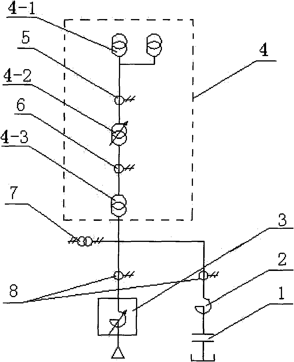
[0012] see figure 1 , the embodiment of a kind of magnetron reactor testing method of the present invention, the series loop that capacitor bank 1 and reactor 2 are formed is connected with magnetron reactor 3 in parallel and connected to test transformer 4, and test transformer 4 is composed of power transformer 4-1 , a voltage regulating transformer 4-2, a step-up transformer 4-3 and a current transformer 5,6. When the capacity of the test transformer 4 is insufficient, the capacitive reactive power of the capacitor bank 1 is used to compensate the test transformer 4, so that the magnetron reactor 3 is tested under full load. The test process adopts the parallel resonance method. Firstly, the output voltage of the test transformer 4 is adjusted, and then the control pulse output by the controller of the magnetic control reactor 3 is changed to change the output capacity of the magnetic control reactor 3 so that it is compatible with the capacitor bank 1 and the reactance. T...


PUM


Abstract

The invention provides a test method of a magnetically controlled reactor, which is characterized in that a serial circuit consisting of a capacitor bank and a reactor is connected with a magneticallycontrolled reactor in parallel and then is connected to a test transformer, a parallel resonant method is utilized, and capacitive reactive power of the capacitor bank is utilized to compensate the test transformer when the capacity of the test transformer is in short. When in low voltage, the output capacity of the magnetically controlled reactor is adjusted to ensure that the output capacity isslightly larger than the capacity of the compensated capacitor bank; and when in low voltage and small capacity, resonance points are evaded so as to protect the test equipment and avoid adverse results caused by resonance. Then voltage is boosted, the output capacity of the magnetically controlled reactor is adjusted to lead the output capacity of the test transformer to be minimum; and the voltage is continuously boosted, inductance is adjusted until the voltage and output power born by the magnetically controlled reactor meet test requirements. The test method ensures that the magneticallycontrolled reactor can satisfy design requirement when leaving the factory and run reliably and safely on site, thereby preventing the equipment from doing experiments on the site of a transformer substation and greatly saving manufacturing costs.

Description

technical field [0001] The invention belongs to a test method for a magnetron reactor (abbreviated as MCR) in a power system, which is mainly used for the test of the magnetron reactor after manufacturing, and belongs to the technical field of power system products. Background technique [0002] After the production and manufacture of the magnetron reactor is completed, routine testing and testing must be carried out. At present, the test of the magnetron reactor in the power system in the production plant cannot achieve the rated voltage and rated load state, that is, it cannot simulate the actual use conditions. The main reason is that the capacity of the magnetic control reactor is increasing day by day, and the test equipment of general enterprises has certain limitations. Taking the magnetic control reactor of model BKSF-12000 / 35 as an example, it is necessary to simulate the actual use conditions for it. , it is necessary to have a transformer with a voltage of 35kV an...

Claims


Application Information

Patent Timeline
Patent Type & Authority Applications(China)
IPC IPC(8): G01R31/00
Inventor 王波贺应华
Owner QINGDAO ZHONGZI ZHONGCHENG GROUP CO LTD
Why Eureka
Try Eureka