DC (direct current) circuit breaker rapid operating mechanism with current limiting characteristic

A DC circuit breaker and operating mechanism technology, applied in the field of electrical machinery, can solve the design requirements that the energy of the repulsion disc cannot be effectively used, the speed of the moving contact is accelerated, and the operating mechanism of the DC circuit breaker cannot meet the design requirements of faster and more reliable breaking and other issues to achieve the effect of reducing quality, protecting electrical equipment, and reducing impact

Inactive Publication Date: 2013-07-03
XI AN JIAOTONG UNIV +1
View PDF5 Cites 2 Cited by
  • Summary
  • Abstract
  • Description
  • Claims
  • Application Information

AI Technical Summary

Problems solved by technology

[0005] The technical purpose of the present invention is to overcome the technical problem in the prior art that the DC circuit breaker operating mechanism cannot meet the design requirements for faster and more reliable breaking
At the same time, it also solves the technical problem that the energy of the repulsion disk cannot be effectively used during the use of the ordinary electromagnetic repulsion mechanism; it provides a method that can effectively use the energy of the repulsion disk movement, speed up the rigid separation speed of the moving contact, and reduce the load on the mechanical structure of the release. Electromagnetic repulsion mechanism of DC circuit breaker to improve breaking performance of circuit breaker

Method used


Image

  • DC (direct current) circuit breaker rapid operating mechanism with current limiting characteristic
  • DC (direct current) circuit breaker rapid operating mechanism with current limiting characteristic
  • DC (direct current) circuit breaker rapid operating mechanism with current limiting characteristic

Examples


Embodiment Construction

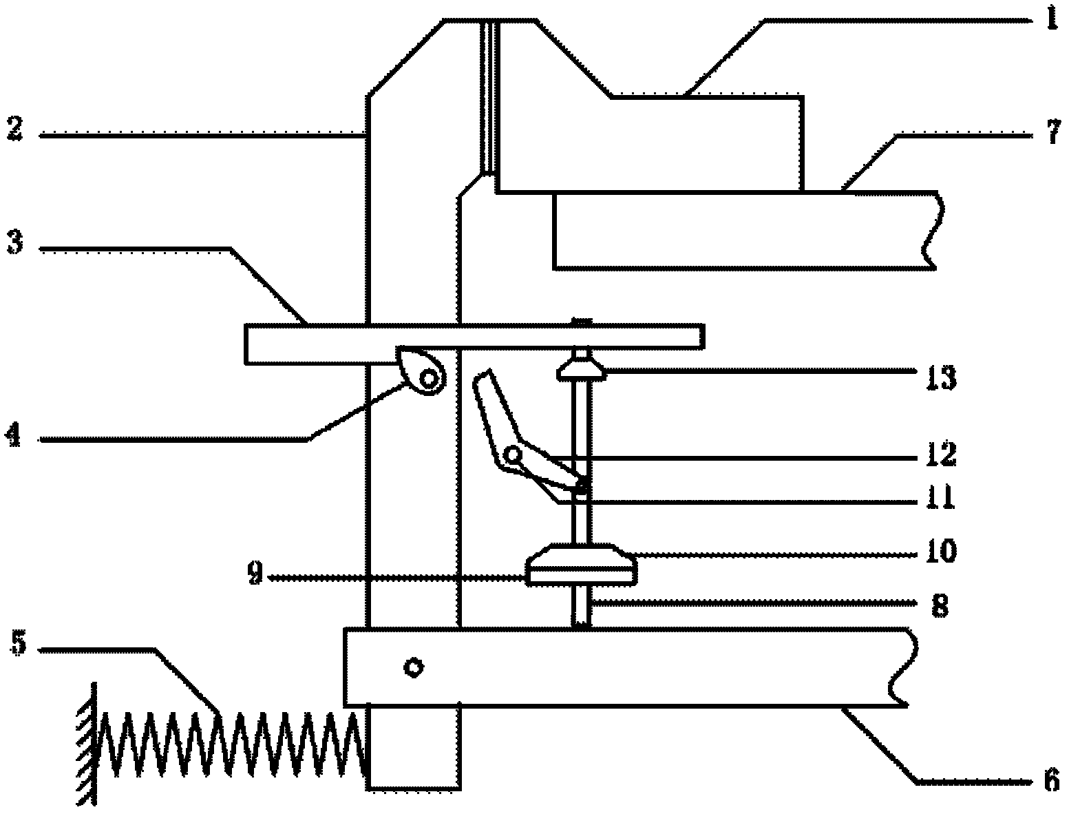
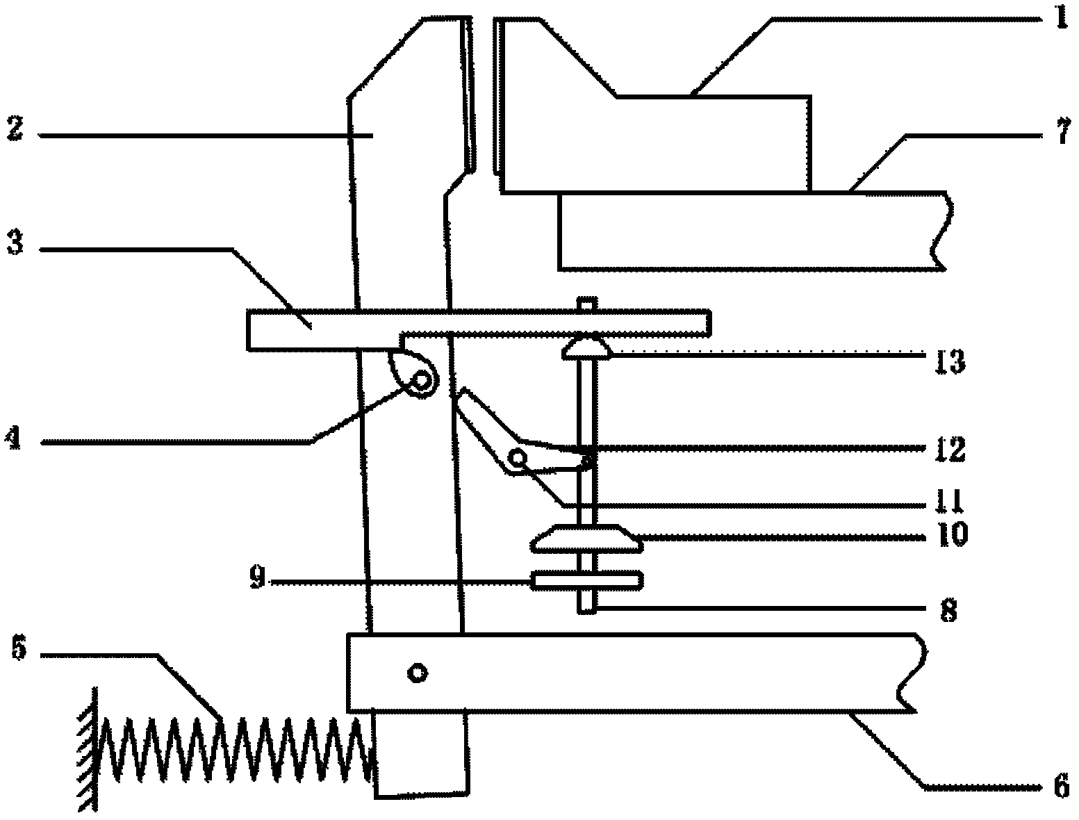
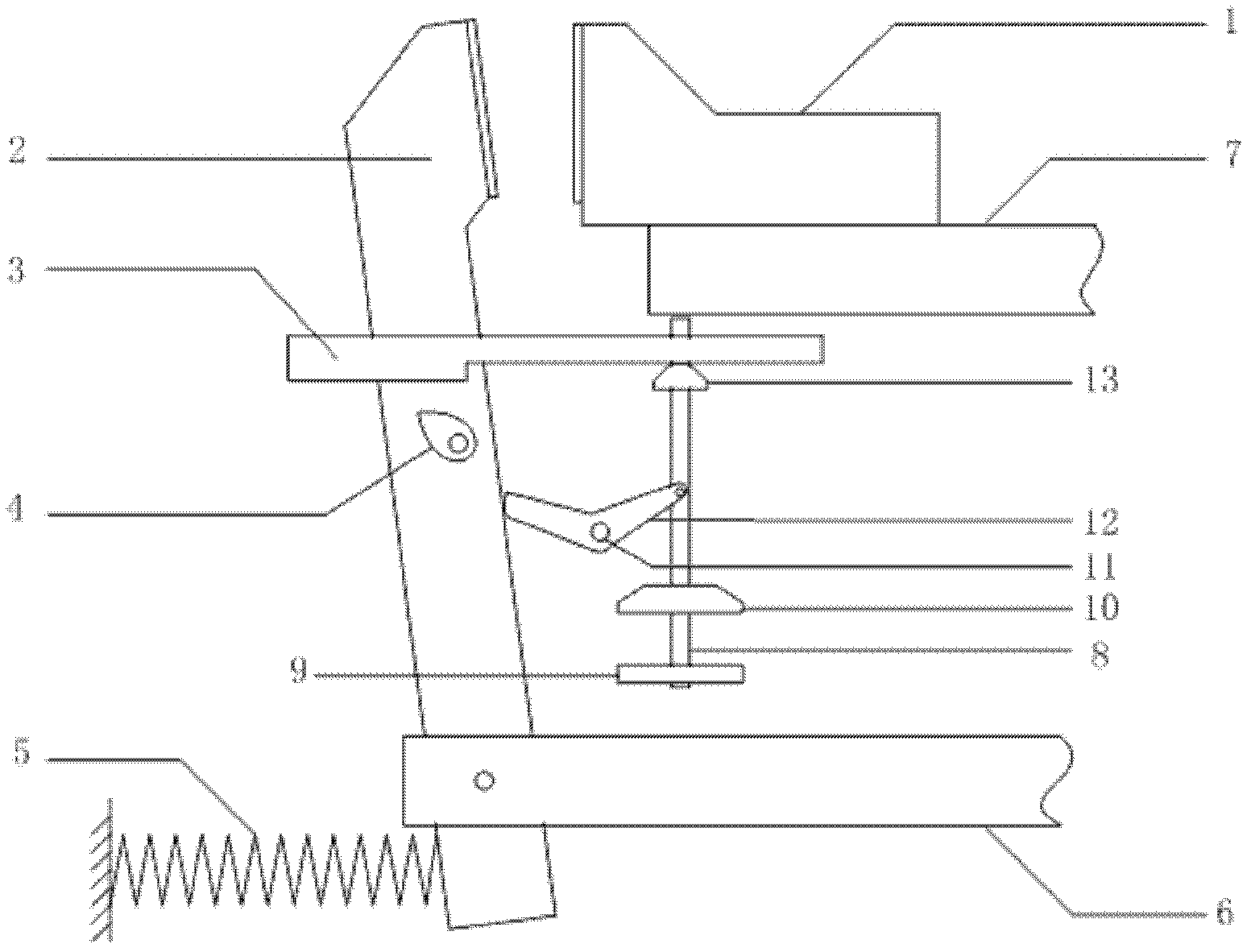
[0017] See attached figure 1 , attached figure 2 , attached image 3 As shown, the present invention is mainly composed of a DC circuit breaker contact system and an electromagnetic repulsion operating mechanism.

[0018] The DC circuit breaker contact system of the present invention includes a static contact 1 and a moving contact 2. The static contact 1 is fixed on the upper busbar 7, and the moving contact 2 is fixed on the lower busbar 6 through a rotating shaft. The contact 1 is in electrical contact with the moving contact 2; on the lower side of the moving contact 2, there is a compressed opening spring 5, and the function of the opening spring is mainly to ensure the movement speed of the moving contact in the later stage of the opening. ; The middle part of the moving contact 2 is provided with a block 4, and the block 4 is stuck in the notch of the shift fork push rod 3 in the closing state to play a position-limiting role, so that the moving contact 2 cannot be l...


PUM


Abstract

The invention discloses a DC (direct current) circuit breaker rapid operating mechanism with the current limiting characteristic, which comprises a fixed contact and a moving contact. The fixed contact and the moving contact are kept in electrical connection in a switching-on state. The moving contact is fixed on a lower busbar by a rotating shaft and a compressed switching-off spring is arrangedat the lower side of the moving contact. A bump at the middle part of the moving contact is clamped in a notch of a shifting fork push rod to take a limiting effect so as to ensure the shifting fork push rod not to move. One side of the moving contact is provided with a switching-off coil and a repulsive force disk and the repulsive force disk is connected with a connecting rod. The side of the connecting rod, which is close to the moving contact, is provided with a crank arm, the crank arm can rotate around a fixed rotating shaft and one arm of the crank arm is connected with the connecting rod by a straight line through hole. The DC circuit breaker rapid operating mechanism is characterized in that when a circuit breaker is switched off, the repulsive force disk drives the connecting rod to move to trigger a release so that the moving contact starts to move, and simultaneously, the connecting rod drives the crank arm to rotate and is collided with the moving contact, so that the moving speed of the moving contact is fastened and the on-off characteristic of the circuit breaker is improved. The DC circuit breaker rapid operating mechanism has ingenious structure design, simple structure and reliable performances.

Description

technical field [0001] The invention belongs to the field of electrical machinery, and relates to a quick operating mechanism of a DC circuit breaker, in particular to a quick operating mechanism of a DC circuit breaker with current limiting characteristics, which utilizes the motion energy of a repulsive disk for auxiliary breaking. Background technique [0002] In recent years, DC power supply systems in my country's subways, light rails, ships, solar energy and other fields have developed rapidly. In order to meet the protection requirements in DC power distribution systems, the development of fast DC switches has become an inevitable trend. When a short-circuit fault occurs in the DC power supply system, the short-circuit current will quickly reach a peak value and oscillate to finally reach a steady-state value. The electrodynamic effect and thermal effect produced by the huge short-circuit current will cause serious damage to the electrical equipment in the system. If...

Claims


Application Information

Patent Timeline
Patent Type & Authority Patents(China)
IPC IPC(8): H01H71/10H01H71/24
Inventor 杨飞赵鸿飞荣命哲袁端磊陈骏星溆王海燕
Owner XI AN JIAOTONG UNIV
Why Eureka
Try Eureka