Micro-nano fiber bragg grating refractive index sensor and manufacturing method thereof

A technology of refractive index sensor and Bragg grating, which is applied in the direction of phase influence characteristic measurement, etc., can solve the problems affecting the popularization and application of long-period fiber Bragg grating refractive index sensors, reduce the multiplexing ability of fiber Bragg grating refractive index sensors, limit the accuracy of refractive index measurement, etc. problem, to achieve the effect of fast measurement, simple structure and accurate sensitivity

Inactive Publication Date: 2013-01-16
XI'AN PETROLEUM UNIVERSITY
View PDF7 Cites 20 Cited by
  • Summary
  • Abstract
  • Description
  • Claims
  • Application Information

AI Technical Summary

Problems solved by technology

Although the long-period fiber grating (LPG) has high sensitivity to the change of the refractive index of the surrounding medium and can eliminate the limitations of application environment conditions such as small space, corrosion and electromagnetic interference, there are problems such as multi-resonant peaks and large transmission peak bandwidth, which limits the The accuracy of refractive index measurement reduces the multiplexing capability of fiber grating refractive index sensors and affects the popularization and application of long-period fiber grating refractive index sensors

Method used


Image

  • Micro-nano fiber bragg grating refractive index sensor and manufacturing method thereof
  • Micro-nano fiber bragg grating refractive index sensor and manufacturing method thereof
  • Micro-nano fiber bragg grating refractive index sensor and manufacturing method thereof

Examples


Embodiment 1

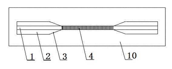
[0031] see figure 1 , a micro-nano fiber Bragg grating refractive index sensor, including a plexiglass plate 10, the plexiglass plate 10 is fixedly connected with the two ends of the fiber Bragg grating 1, and the middle section of the fiber Bragg grating 1 is an unclad core grating region 4 .

[0032] The fiber Bragg grating 1 is an ordinary fiber Bragg grating.

[0033] The fiber Bragg grating 1 is a micro-nano fiber Bragg grating.

[0034] The diameter of the cladding-free core grid region 4 is on the order of 1-8 μm.

[0035] The two ends of the organic glass plate 10 and the fiber Bragg grating 1 are fixedly connected with paraffin.

[0036] The micro-nano optical fiber Bragg grating used in the present invention is an optical fiber Bragg grating with only a core, its diameter is on the order of 1-8 μm, its mechanical strength is relatively good, and the cladding is corroded by hydrofluoric acid.

[0037] A method for manufacturing a micro-nano fiber Bragg grating ref...

Embodiment 2

[0050] A method for manufacturing a micro-nano fiber Bragg grating refractive index sensor, comprising the steps of:

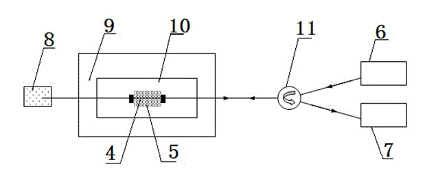
[0051] 1) Fix the two ends of the ordinary fiber Bragg grating on the plexiglass of 10cm×5cm×0.5cm, the direction is along the long side direction, and fix it with paraffin, put it in the adjustable thermostat 9, and control the temperature at 17°C constant temperature;

[0052] 2) Add 0.8ml of hydrofluoric acid dropwise to the cladding of the fiber Bragg grating in step 1), and the etching time is 125 minutes to corrode the cladding of the grating, so that the core of the grating is directly exposed;

[0053] 3) Take out the micro-nano fiber Bragg grating corroded in step 2) together with the plexiglass, suck off the residual corrosion solution with a straw, wash it with clean water, and then apply a 40% NaOH solution for 10 minutes to ensure that the residual hydrofluoric acid Be completely neutralized, and finally rinse with deionized water.

Embodiment 3

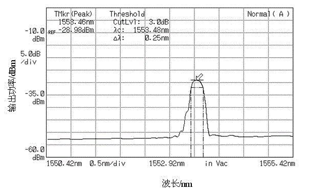
[0055] In this example, by setting the etching time as 15, 30, 45, 60, 75, 90, 105, and 120 minutes respectively, under the constant temperature condition of 20°C, the fiber Bragg The diameter of the grating) of the fiber grating is corroded, and the method and steps used are the same as in embodiment 2. The relationship between the measured diameter of the fiber grating and the change with time is as follows: Figure 4 As shown, the corrosion process is basically in a linear relationship with time, and the linearity reaches 99.5%, and the corrosion rate of the fiber diameter is 0.992 μm / min. Through the above temperature and corrosion rate, the diameter of the micro-nano fiber grating can be controlled, and the required refractive index sensor can be fabricated.


PUM

PropertyMeasurementUnit
diameteraaaaaaaaaa
diameteraaaaaaaaaa
diameteraaaaaaaaaa

Abstract

The invention relates to a micro-nano fiber bragg grating refractive index sensor and a manufacturing method thereof, comprising an organic glass plate which is fixedly connected with two ends of the fiber bragg grating. The middle section of the fiber bragg grating is a clad-free fiber core gate area. The manufacturing method of the micro-nano fiber bragg grating refractive index sensor comprises the steps of 1) fixing two ends of a common fiber bragg grating on an organic glass, putting the organic glass in a temperature-regulated oven, and controlling the temperature at a constant temperature between 17 DEG C and 25 DEG C; 2) dropwise adding 0.8 mL-1.2 mL hydrofluoric acid on the gate area clad of the fiber bragg grating of the step 1), etching for 125-80 minutes, etching off the gate region clad to make the gate area fiber core of the fiber exposed directly; and 3) taking the etched fiber bragg grating of the step 2) together with the organic glass out from the oven, sucking residue etching liquid, cleaning the etched fiber bragg grating, coating a 40% NaOH solution on the etched fiber bragg grating, immersing for 10 minutes to ensure that the residue hydrofluoric acid is neutralized completely, and finally washing the fiber bragg grating with deionized water. The micro-nano fiber bragg grating refractive index sensor has the characteristics of simple structure, accurate measurement and high signal-to-noise ratio.

Description

technical field [0001] The invention belongs to the technical field of optical fiber sensing, and in particular relates to a micro-nano optical fiber Bragg grating refractive index sensor and a manufacturing method thereof. Background technique [0002] The refractive index is one of the commonly used optical parameters. Many physical and chemical parameters of substances are related to the refractive index. Measuring the refractive index has important research significance in petrochemical, environmental monitoring, medical diagnosis and other application fields. The traditional methods for measuring the refractive index include: minimum deflection angle method, Abbe refractometer critical angle method, interferometry, etc. These technical methods are easily limited by space and application environment conditions. With the development of optical fiber sensing technology, due to the characteristics of small size, corrosion resistance, and electromagnetic interference resista...

Claims


Application Information

Patent Timeline
Patent Type & Authority Applications(China)
IPC IPC(8): G01N21/41
Inventor 刘颖刚乔学光贾振安傅海威车伏龙
Owner XI'AN PETROLEUM UNIVERSITY
Why Eureka
Try Eureka