
Wireless switch device and system and communication control method thereof

A wireless switch and timing control technology, applied in electronic switches, signal transmission systems, instruments, etc., can solve problems such as power consumption

Inactive Publication Date: 2010-02-03
TSINGHUA UNIV +1
View PDF3 Cites 13 Cited by
  • Summary
  • Abstract
  • Description
  • Claims
  • Application Information

AI Technical Summary

Problems solved by technology

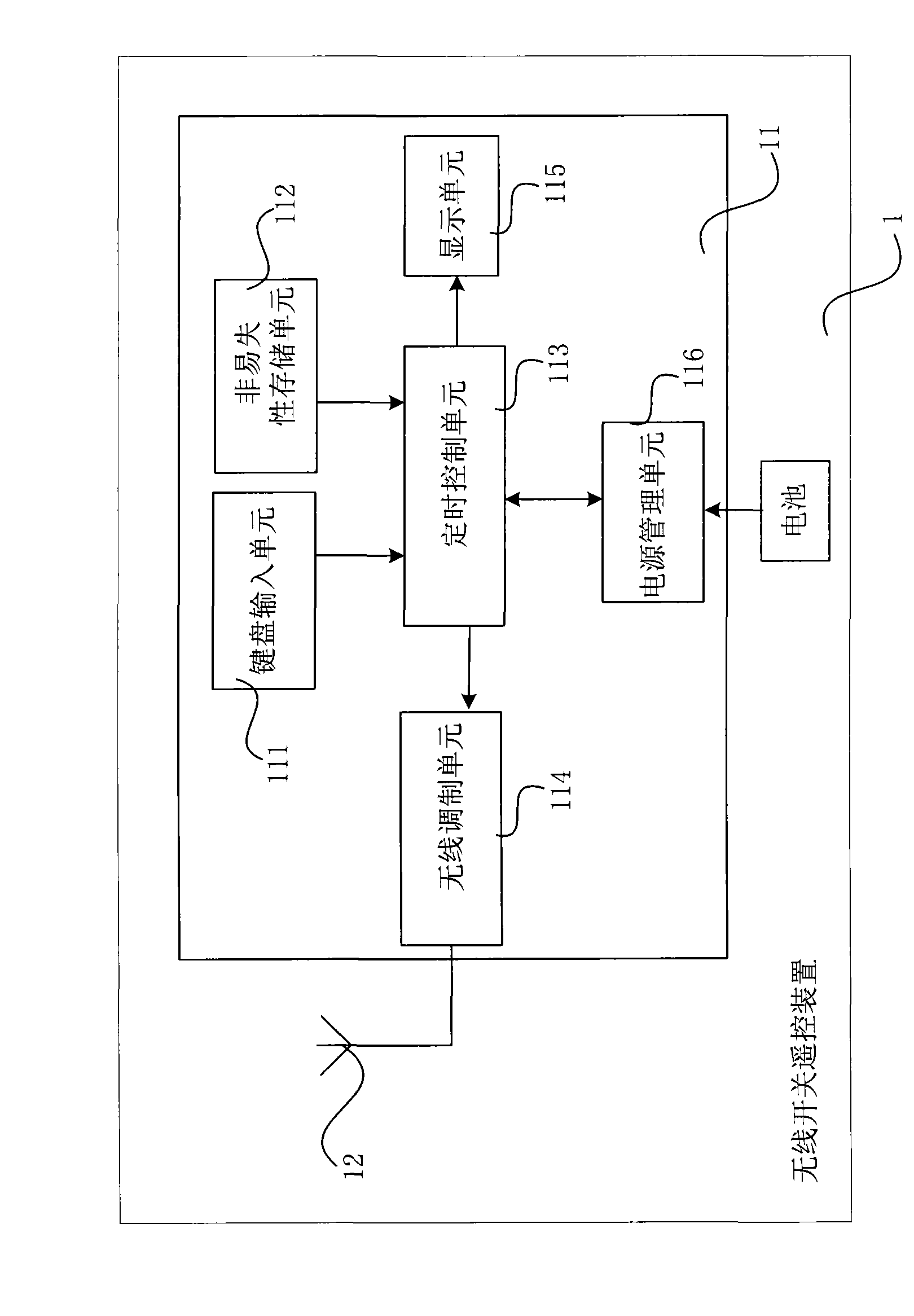
[0007] In order to solve the problems of power consumption in the prior art, the purpose of the present invention is to provide a wireless switch remote control device, so as to realize the transmission of wireless control signals and energy signals carrying identification codes, and remotely control the state of switches in the wireless switch device

Method used


Image

  • Wireless switch device and system and communication control method thereof
  • Wireless switch device and system and communication control method thereof
  • Wireless switch device and system and communication control method thereof

Examples


Embodiment Construction

[0133] The technical solutions of the embodiments of the present invention will be described in further detail below with reference to the drawings and embodiments.

[0134] The invention realizes the control of the wireless switch remote control device on the wireless switch device based on the energy recovery technology, and completely eliminates the standby power consumption of the electronic equipment with the remote control function.

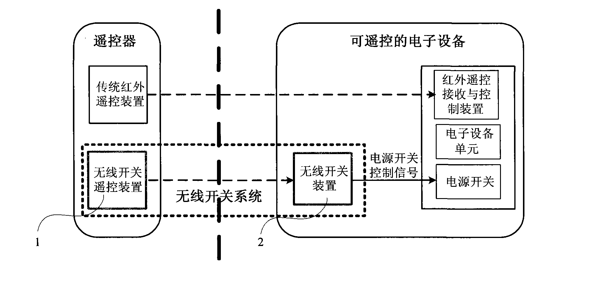
[0135] see first figure 2 Shown is a schematic block diagram of the wireless switch system of the present invention, which includes a wireless switch remote control device 1 and a wireless switch device 2 . The user controls the wireless switch remote control device 1 to transmit the carrier energy signal and the identification code signal and switch control signal uniquely corresponding to the wireless switch device 2 to the wireless switch device 2 through the key operation of the keyboard input unit of the wireless switch remote control...


PUM


Abstract

The invention discloses a wireless switch system comprising a wireless switch remote controller and a wireless switch device. The invention also discloses the wireless switch remote controller comprising a power supply, a signal generating module and a transmission antenna. The invention also discloses the wireless switch device comprising a switch, a reception antenna, an energy restoring moduleand a switch control module. In addition, the invention also discloses a communication control method of the wireless switch system. The communication control method comprises the following steps: thewireless switch remote controller emits a carrier energy signal, a modulated synchronous signal and an instruction data signal; the wireless switch device restores energy from the carrier energy signal; and according to judgment results of an identification code, a control code and a verification code, the wireless switch device outputs a control signal matched with a controlled switch so as to control the connection and disconnection of the switch. Therefore, holding state power consumption of an electronic apparatus with a remote control function can be completely eliminated, and the wireless switch system has a simple design and is easy to directly embed into the electronic apparatus with the remote control function.

Description

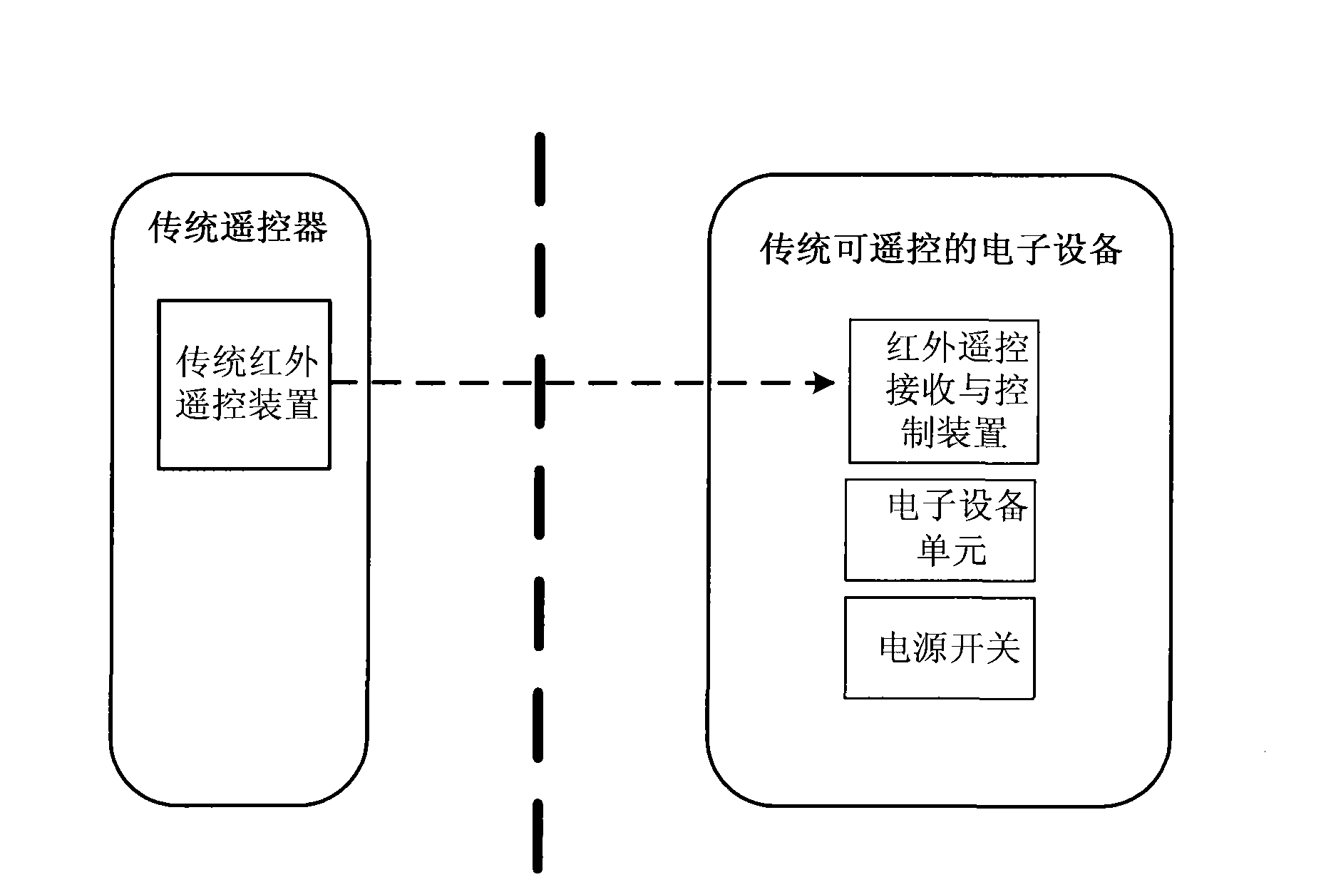
[0001] This application is a divisional application of the invention patent application with the application number 200810084655.6, the application date is March 14, 2008, and the invention title is "a wireless switch device, system and communication control method thereof". technical field [0002] The invention relates to the field of wireless communication and switch control, in particular to a wireless switch remote control device using energy recovery technology, a wireless switch device, a wireless switch system and a communication control method thereof. Background technique [0003] Remote control electronic devices are widely used in today's society, such as air conditioners, water heaters, televisions, etc. First introduce the block diagram of the traditional controllable remote electronic equipment system, such as figure 1 shown. The system is composed of traditional remote control and traditional remote control electronic equipment. It is characterized in that t...

Claims


Application Information

Patent Timeline
Patent Type & Authority Applications(China)
IPC IPC(8): G08C17/02H03K17/94
Inventor 姜汉钧张晓昱张凌伟谢翔张春王志华王红梅
Owner TSINGHUA UNIV
Learn More