Hydraulic shovel

A technology of hydraulic excavators and hydraulic cylinders, which is applied in the field of hydraulic excavators, can solve the problems of poor weight balance and damage of the front device, and achieve the effects of improving weight balance, working stably, and preventing damage

Inactive Publication Date: 2010-02-03
KYB CORP
View PDF2 Cites 14 Cited by
  • Summary
  • Abstract
  • Description
  • Claims
  • Application Information

AI Technical Summary

Problems solved by technology

[0005] However, in such conventional hydraulic excavators, since the control valve is provided on the front unit, there is a problem that the weight balance of the front unit is deteriorated due to the weight of the control valve.
[0006] In addition, since the control valve is installed on the outside of the front unit, there is a possibility that the control valve and the piping of the control valve, etc. may hit obstacles and be damaged during work.

Method used


Image

  • Hydraulic shovel
  • Hydraulic shovel

Examples


Embodiment Construction

[0012] Embodiments of the present invention will be described below with reference to the drawings.

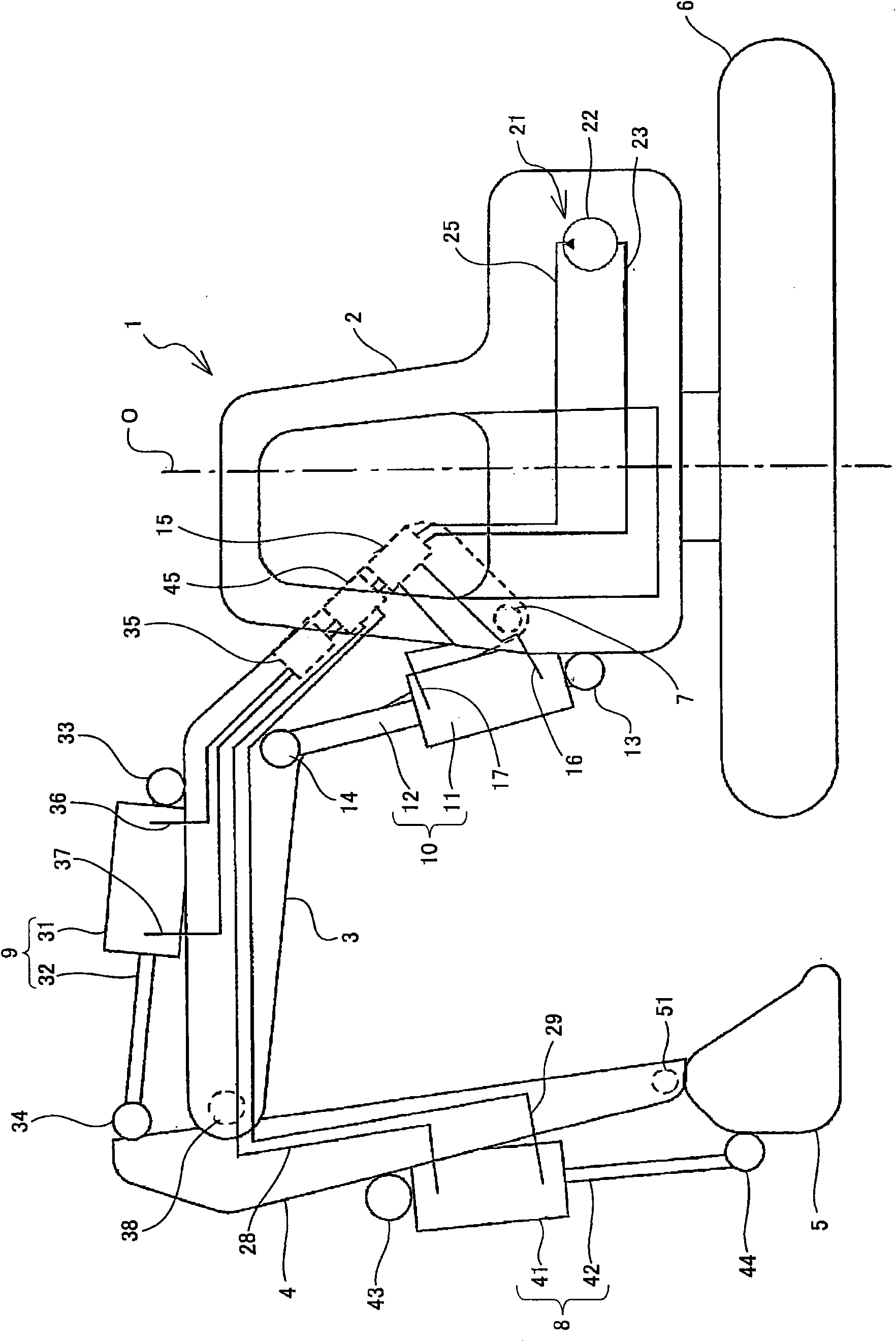
[0013] Such as figure 1 As shown, the hydraulic excavator (construction machine) 1 according to the embodiment of the present invention is provided with a vehicle body (rotary body) 2 rotatable relative to the upper part of the running body 6 .

[0014] The hydraulic excavator 1 has a boom 3 connected to the vehicle body 2 so as to be rotatable relative to the vehicle body 2 via a boom support shaft 7, two boom hydraulic cylinders 10 for driving the boom 3, and The support shaft 38 is rotatably connected to the arm 4 at the top end of the boom 3 , an arm hydraulic cylinder 9 for driving the arm 4 , and is rotatable relative to the arm 3 by means of a bucket support shaft 51 . A bucket 5 connected to the top end of the arm 4 in such a way that the arm 4 rotates, and a hydraulic cylinder 8 for the bucket to drive the bucket 5 .

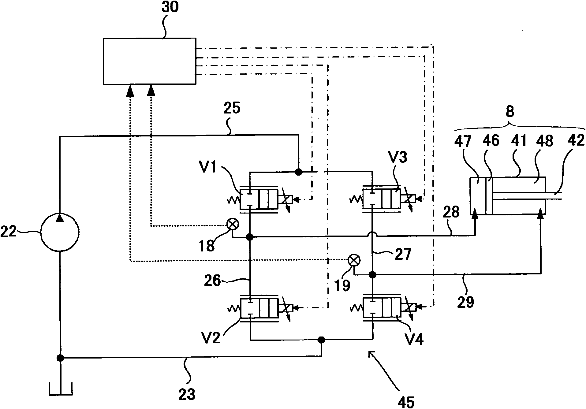
[0015] A hydraulic pressure source unit 21 is m...


PUM


Abstract

A hydraulic shovel (1) in which a vehicle body (2) is so mounted on a traveling body (6) as to be capable of revolving comprises a boom (3) rotatably connected to the vehicle body (2); an arm (4) rotatably connected to the boom (3), a bucket (5) rotatably connected to the arm (4); a boom hydraulic cylinder (10) for driving the boom (3); an arm hydraulic cylinder (9) for driving the arm (4), a bucket hydraulic cylinder (8) for driving the bucket (5); and a boom control valve (15), an arm control valve (35) and a bucket control valve (45) for controlling the flow rates of the hydraulic oil supplied to and discharged from the respective hydraulic cylinders (8, 9, 10). The boom (3) is formed in a hollow-shape, and the bucket control valve (45) is disposed inside the boom (3).

Description

technical field [0001] The invention relates to a hydraulic excavator, which drives a front device composed of a boom, an arm and a bucket through a hydraulic cylinder. Background technique [0002] As a hydraulic excavator in the prior art, some hydraulic excavators are provided with distributed control valves on their front devices, and the flow of operating oil supplied to and discharged from each hydraulic cylinder is controlled by each control valve (refer to Japanese Patent Application Laid-Open). 2004-293089 bulletin, JP-A 2005-68718 bulletin). [0003] In the hydraulic excavator disclosed in Japanese Patent Application Laid-Open No. 2004-293089, each control valve is arranged in the vicinity of each hydraulic cylinder for driving the front device. [0004] In the hydraulic excavator disclosed in Japanese Patent Application Laid-Open No. 2005-68718, each control valve is arranged in a row on the outer side of the boom. [0005] However, in such conventional hydrauli...

Claims


Application Information

Patent Timeline
Patent Type & Authority Applications(China)
IPC IPC(8): E02F9/00E02F3/36
CPCE02F9/2285E02F9/2267E02F9/226E02F9/2228E02F3/36E02F9/2264E02F3/42E02F9/14E02F9/20
Inventor 小畑宏
Owner KYB CORP
Why Eureka
Try Eureka