Guide wire

A technology of guide wire and wire material, which is applied in the field of guide wire with welding structure in the main body, which can solve the problems of complex manufacturing process, high hardness of tubular parts, and affecting the continuity of elasticity, so as to reduce the possibility of vascular injury and increase the welding Combining the area and the effect of improving safety in use

Inactive Publication Date: 2010-02-10
LEPU MEDICAL TECH (BEIJING) CO LTD
View PDF0 Cites 11 Cited by
  • Summary
  • Abstract
  • Description
  • Claims
  • Application Information

AI Technical Summary

Problems solved by technology

[0003] Using one material as a whole cannot achieve this goal. For example, in the prior art, a guide wire made entirely of nickel-titanium alloy will have a certain loss in pushability and operability at the base end.
Some guide wires are all made of rigid materials. Although heat treatment is performed at the distal end to obtain appropriate flexibility, the flexibility obtained in this way has a certain limit and cannot reach the performance of superelastic alloys.
[0004] Another kind of guide wire uses a sleeve to connect stainless steel and nickel-titanium alloy. This is more complicated in the manufacturing process, and the hardness of the tubular part is higher. It is a hard knot in the length direction of the guide wire, which affects the continuity of the elasticity in the length direction.
In addition, the stainless steel and nickel-titanium alloy wires need to be finely ground when they enter the casing. This part cannot completely transmit the torsional force during the use of the guide wire and has certain safety hazards.
[0005] There is also a guide wire that uses the butt welding method to weld the two parts of the guide wire body together. For the guide wire, the diameter is small, the contact area of ​​the butt welding is small, the welding strength is low, and there are potential safety hazards.

Method used


Image

  • Guide wire
  • Guide wire

Examples


Embodiment Construction

[0016] The specific embodiments of the present invention will be described in further detail below in conjunction with the drawings and embodiments. The following examples are used to illustrate the present invention, but not to limit the scope of the present invention.

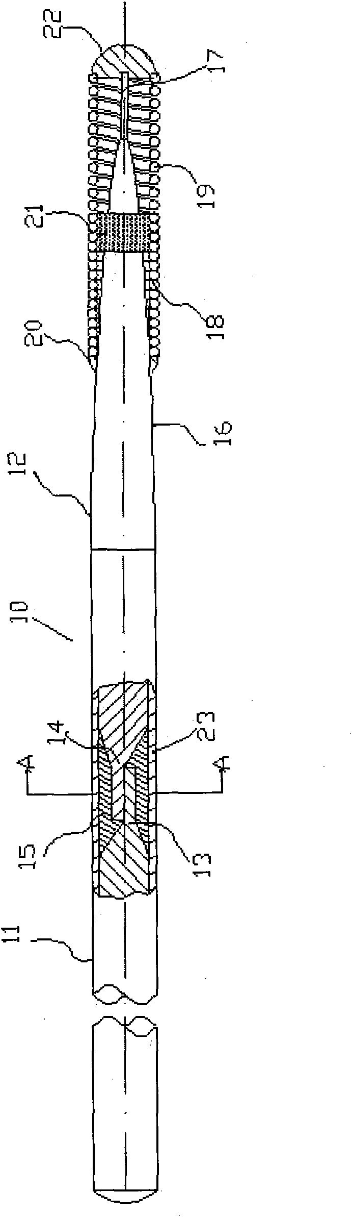
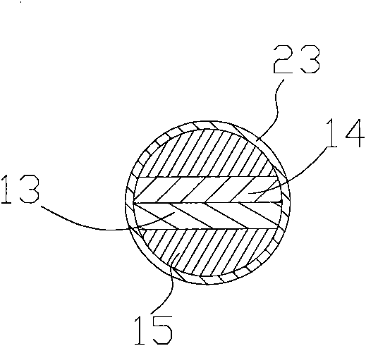
[0017] figure 1 Is a front view showing an embodiment of the guide wire of the present invention, figure 1 The guide wire shown has a guide wire main body 10 and a spring coil 18 and a developed spring coil 19 arranged in sequence at the distal end of the guide wire main body. The guide wire main body 10 is composed of a main structure wire 11 disposed at the proximal end of the guide wire and The main structure wire 12 at the distal end of the guide wire is formed by welding.

[0018] The length of the guide wire body 10 is 90 to 500 cm, preferably 175 cm to 200 cm.

[0019] The outer diameter of the proximal wire 11 of the main structure is uniform, and the distal end of the distal wire 12 of the main structure i...


PUM

PropertyMeasurementUnit
lengthaaaaaaaaaa
diameteraaaaaaaaaa

Abstract

The invention discloses a guide wire. The body of the guide wire comprises a near-end wire with good rigidity and a hyperelastic soft far-end wire, wherein the far-end side of the near-end wire and the base end side of the far-end wire respectively contain a flat surface. The flat surface of the near-end wire and the flat surface of the far-end wire are coincident and are connected by welding. Theguide wire structure adopts a welding method to combine the far-end wire rich in elasticity and the near-end wire with high rigidity, which ensures the obtained guide wire to have enough flexibilityand restoration property at the far end and have good push performance and twisting control performance at the near end, thereby lowering the possibility of the damage to blood vessels by the guide wire and enabling the guide wire to smoothly reach a diseased region. Moreover, due to increasing the welding combination area and effectively transferring a weak stress surface, the connection safety of the guide wire is increased.

Description

Technical field [0001] The invention relates to the technical field of medical devices, and in particular to a guide wire with a welding structure on the main body used in interventional therapy. Background technique [0002] The guide wire plays a role in guiding and positioning various interventional medical catheters and implanted devices in the process of interventional treatment (for example, in percutaneous coronary angiogenesis). It is an indispensable supporting product for diagnosis and interventional devices. According to its function, the ideal guide wire requires flexibility and high resilience at its tip, so that it can show good passability in curved blood vessels, and its base end requires good pushability and high elasticity. And twist control. [0003] Such a purpose cannot be achieved by using one material as a whole. For example, a guide wire made entirely of nickel-titanium alloy in the prior art has a certain loss in the pushability and operability of the base...

Claims


Application Information

Patent Timeline
Patent Type & Authority Applications(China)
IPC IPC(8): A61M25/09A61L31/02A61L31/18
Inventor 张田宏杨永森刘万兵
Owner LEPU MEDICAL TECH (BEIJING) CO LTD
Why Eureka
Try Eureka