
Laser welding protective nozzle

A protective gas nozzle and laser welding technology, which is applied to laser welding equipment, welding equipment, metal processing equipment, etc., can solve the problems that the protection effect cannot meet the welding requirements, the gas protection cannot meet the requirements, and the work efficiency is low. Good welding protection effect, saving shielding gas and uniform gas outlet

Inactive Publication Date: 2010-02-10
SHENYANG INST OF AUTOMATION - CHINESE ACAD OF SCI
View PDF0 Cites 7 Cited by
  • Summary
  • Abstract
  • Description
  • Claims
  • Application Information

AI Technical Summary

Problems solved by technology

Since the two gas outlet pipes and the laser light emitting point are collinear, gas protection can only be carried out in the straight line welding and the welding direction is on the extension line of the three collinear; and in the direction perpendicular to the collinear of the three and on the welding circle When it is out of shape, the gas protection will not meet the requirements
In addition, although gas outlet pipes are installed on both sides of the laser light exit point, the two gas outlet pipes are fed with the same inert gas; different shielding gases have different protective effects on the weld seam, and the gas with better protection effect is better than the other. Expensive, but low-cost gas shielding effect does not meet the welding requirements. When welding encounters different protective effects, the shielding gas needs to be replaced, which is complicated to operate and low in efficiency.

Method used


Image

  • Laser welding protective nozzle
  • Laser welding protective nozzle
  • Laser welding protective nozzle

Examples


Embodiment Construction

[0017] The present invention will be described in further detail below in conjunction with the accompanying drawings.

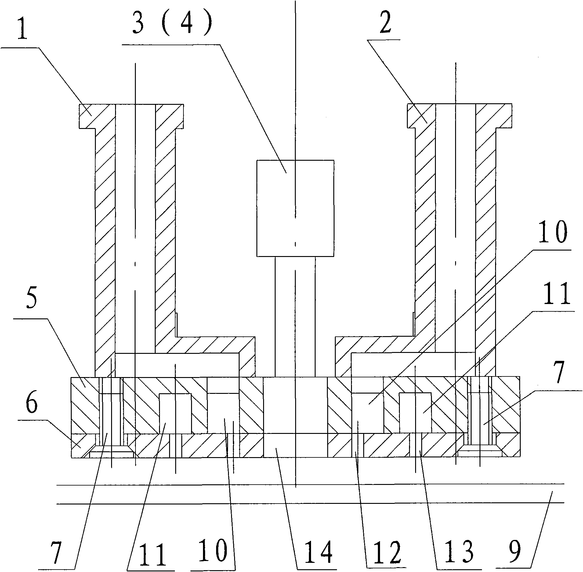
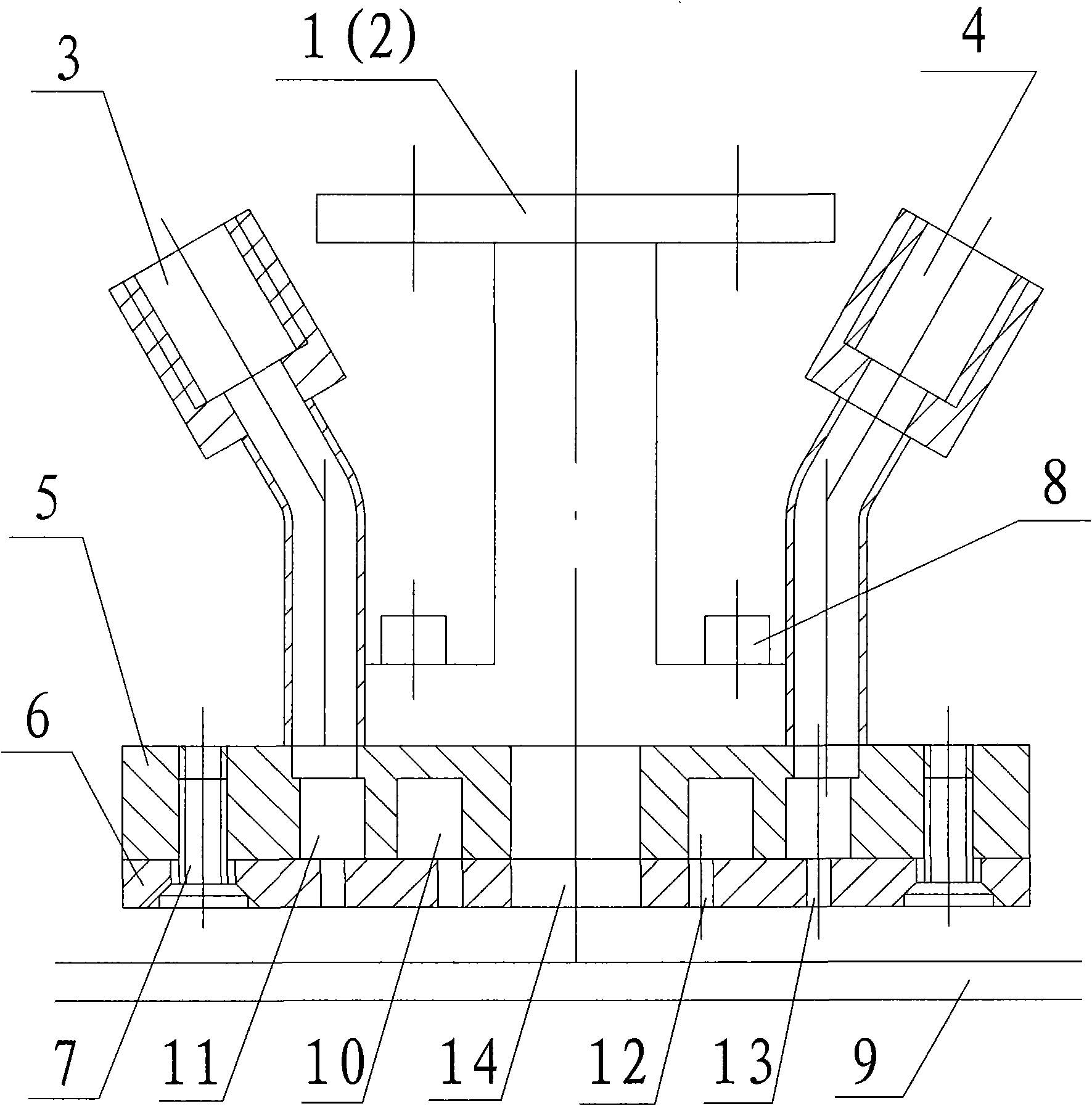
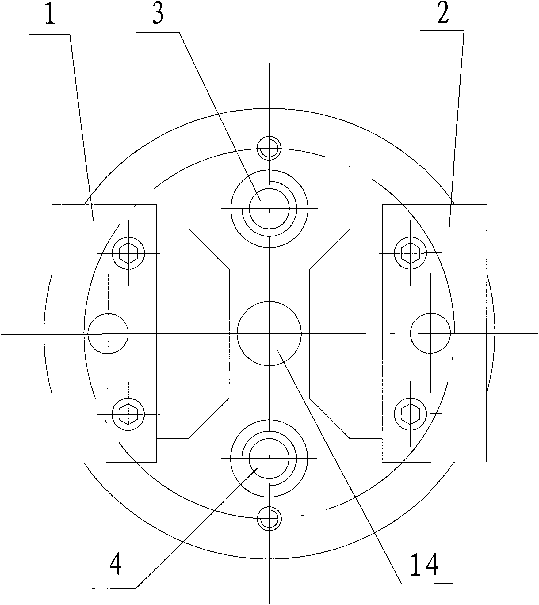
[0018] Such as Figure 1~3 As shown, the present invention is installed on the bottom of the parabolic focusing laser head, including a cavity plate 5 and a base plate 6, the cavity plate 5 is circular, and the center of the cavity plate 5 has a laser passing hole 14, and the laser passing hole 14 The periphery is provided with first and second cavities 10 and 11 from inside to outside. The first and second cavities 10 and 11 are arranged coaxially with the center of the laser passing hole 14 as the center, and both cavities are circular, form a ring, and are relatively independent. The bottom plate 6 is circular, and its diameter is the same as that of the cavity plate 5; a laser passing hole 14 is opened in the center of the bottom plate 6, and a plurality of first holes communicating with the first cavity 10 are evenly distributed on the periphery of the ...


PUM


Abstract

The invention relates to laser welding equipment, in particular to a laser welding protective nozzle capable of protecting welding seams to improve welding quality, which comprises a cavity board, a bottom board connected with the underside of the cavity board, wherein both the cavity board and the bottom board are provided with a laser through hole; inner and outer two mutually independent cavities are arranged on the periphery of the laser through hole of the cavity board respectively; two groups of air holes communicated with two cavities respectively are correspondingly arranged on the periphery of the laser through hole of the bottom board; and two groups of air ducts are arranged above the cavity board, one group of air ducts are communicated with one group of air holes on the bottomplate through one cavity, and the other group of air ducts are communicated with the other air holes on the bottom board through the other cavity. The protective nozzle has the advantages that: a dual-air-path design allows one nozzle to spray two protective gases at the same time; as the air paths, air cavities and an air outlet in the nozzle are reasonably designed, the air exhaust is even andcan effectively protect straight welding seams and curved welding seams; and the protective gases are saved and welding cost is reduced on the premise of ensuring protection effect.

Description

technical field [0001] The invention relates to laser welding equipment, in particular to a laser welding protective gas nozzle for protecting welding seams and improving welding quality. Background technique [0002] In the process of laser welding equipment debugging, such as laser welding of stainless steel plates, it is required to protect the weld seam with gas during laser welding to prevent the weld seam from being oxidized and affecting the welding quality. Through the gas protection of the weld seam, the pressure of the weld seam can be increased, and finally the color of the weld seam is silvery white or golden yellow, and the withstand pressure is 9MPa. [0003] In the existing gas protection, gas outlet pipes are arranged symmetrically on both sides of the laser light exit point, and the other end of the gas outlet pipe is connected to a gas source; the gas is inert gas. Since the two gas outlet pipes and the laser light emitting point are collinear, gas protect...

Claims


Application Information

Patent Timeline
Patent Type & Authority Applications(China)
IPC IPC(8): B23K26/42B23K26/12B23K26/14
Inventor 刘勇甘洪岩吴强池世春徐志刚
Owner SHENYANG INST OF AUTOMATION - CHINESE ACAD OF SCI
Learn More