
Floating swing type wave energy conversion device

An energy conversion device, floating technology, applied in ocean energy power generation, engine components, machines/engines, etc., can solve the problems of many intermediate links of electric energy, high power generation cost, wave energy absorption, etc., to achieve high energy conversion rate, structure Simple and reliable, a wide range of effects

Inactive Publication Date: 2010-02-10
张益
View PDF0 Cites 16 Cited by
  • Summary
  • Abstract
  • Description
  • Claims
  • Application Information

AI Technical Summary

Problems solved by technology

[0009] Although these three types have their own advantages, their common disadvantages are: 1. There are many intermediate links for converting wave energy into electrical energy, which is inefficient and difficult to form a scale; 2. Only part of the mechanical energy of waves can be used, and disordered Distributed, low-density, unstable wave energy can be absorbed, and the cost of power generation is high; 3. The wave energy conversion device and its structures have poor ability to withstand disastrous marine climate, and it is not easy to resist the damage of typhoon and tsunami, which poses a safety hazard larger
[0010] Recently, the United Kingdom and other Western European countries have developed buoy-type sea snake technology. They use several buoys connected in series to ride on the waves, and use the changes in the undulating slope angle of the waves to push the pistons of the buoys to generate electricity. This method can indeed make the system The wind and wave resistance can be enhanced, but because the undulation of the wave itself is very gentle, the angle change is also small, and it is perpendicular to the wave crest line, so a string of buoys can only correspond to waves with a small width, and the efficiency is not ideal. Its ability to resist typhoons and tsunamis is not enough, and the above shortcomings have not been overcome.
[0011] Due to various technical problems, wave power generation costs 10 times higher than thermal power and has hidden dangers

Method used


Image

  • Floating swing type wave energy conversion device
  • Floating swing type wave energy conversion device

Examples


Embodiment Construction

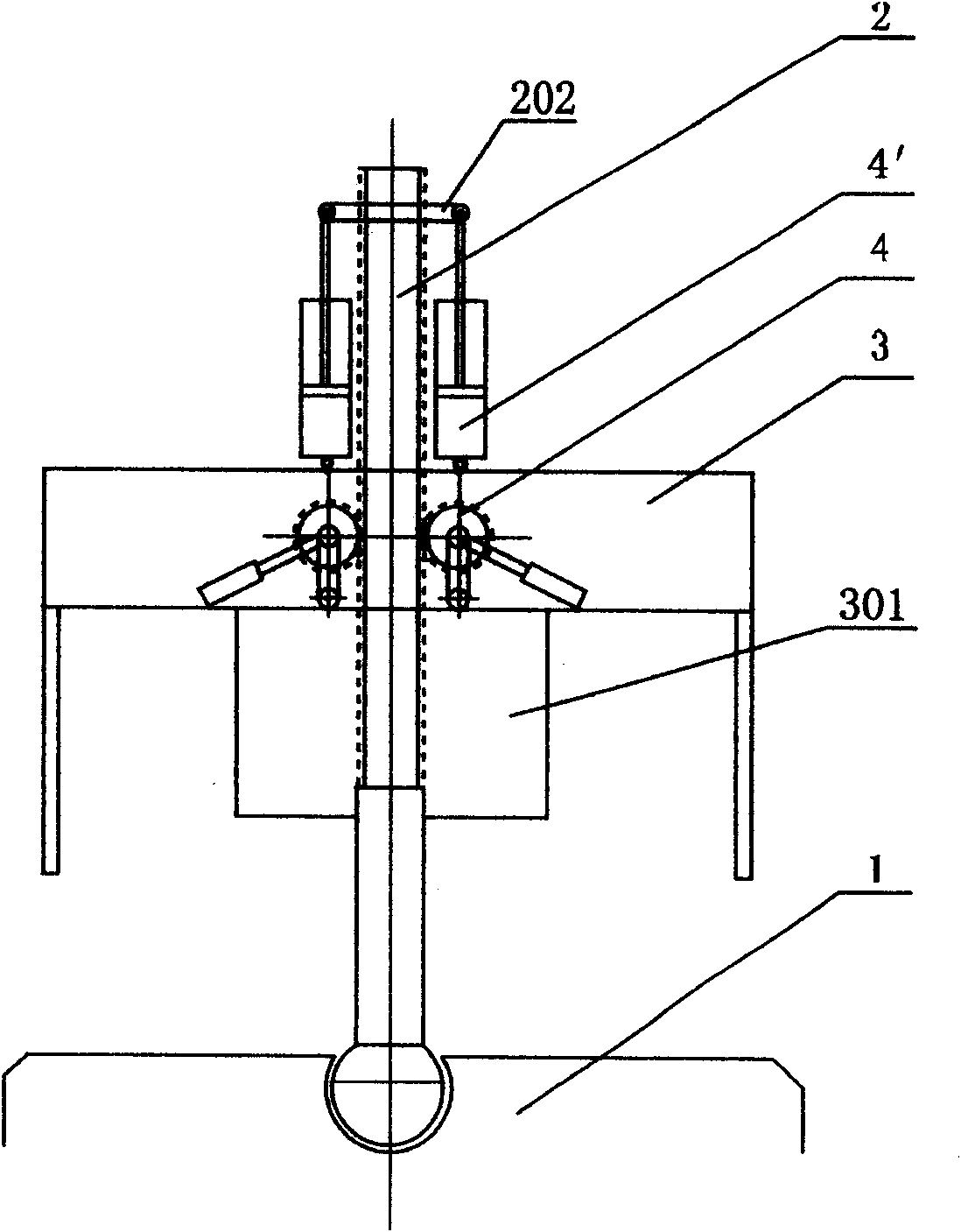
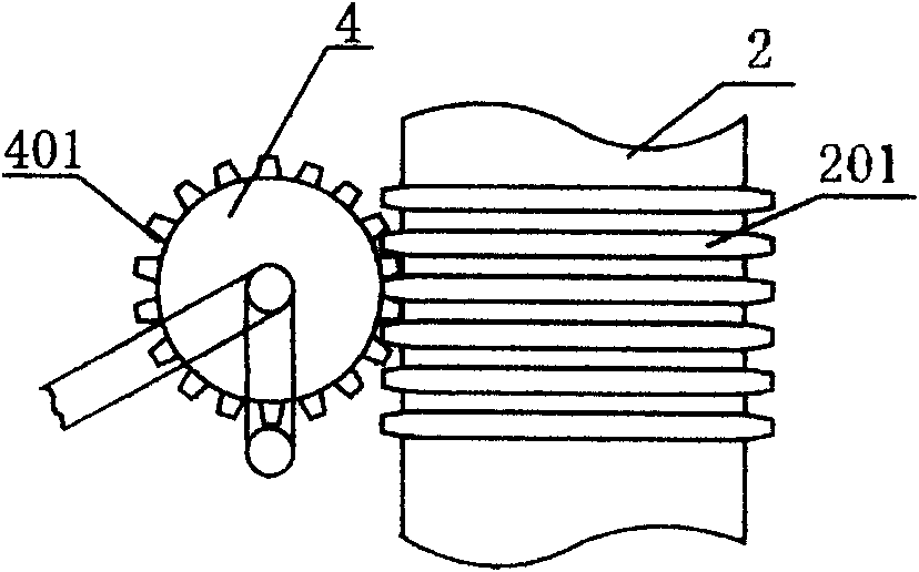
[0026] see figure 1 , the floating and swaying wave energy conversion device is composed of a seabed fixed seat 1, a swaying support 2, a floating energy harvesting device 3 and a transducer 4, which is characterized in that the working parts of the transducer 4 are between the floating energy harvesting device 3 and the transducer 4. Between the swaying pillars 2, energy conversion is realized through transmission devices such as gears and racks or tension-compression elastic devices.

[0027] Since the ocean wave is a kind of disorderly movement that goes up and down, left and right, big and small, and the water level is high and low, and changes constantly. Therefore, in order to fully collect these energies, it is necessary to make the waves fully act on an object. Doing work, transferring energy to the object, the simplest way is to act on a floating object. In order to transfer the energy obtained by the floating objects to the working machine and prevent the floating o...


PUM


Abstract

The invention discloses a floating swing type wave energy conversion device for converting unordered mechanical energy of wave into available kinetic energy or potential energy, which consists of a seabed fixed seat, a swing strut, a floating energy collection device and an energy converter, and is characterized in that a working component of the energy converter is positioned between the floatingenergy collection device and the swing strut, and energy conversion is realized through a gear chain transmission device or a tension and compression elastic device. The device has the characteristics of little middle link, high energy conversion rate and the like, and can be used for generating electricity or directly applying work.

Description

technical field [0001] The invention relates to an energy conversion device, in particular to a floating and swaying ocean wave energy conversion device which converts disordered mechanical energy of ocean waves into available kinetic energy or potential energy. Background technique: [0002] The ocean area accounts for 71% of the earth's surface. Ocean wave energy is the most abundant, most common, inexhaustible, inexhaustible, and most reliable resource that is better utilized in ocean energy. Wave energy is the ocean energy with the largest proportion in ocean energy. The wave motion of sea water produces very huge energy. It is estimated that the wave energy that is relatively easy to use in the world's oceans reaches more than 70 billion kilowatts, accounting for more than 94% of all ocean energy. [0003] China is a country with a long coastline and high availability of waves. The density of wave energy in coastal provinces such as Hainan Island, Taiwan, Fujian, Zheji...

Claims


Application Information

Patent Timeline
IPC IPC(8): F03B13/16
CPCY02E10/38Y02E10/30
Inventor 张吉林卓小勤张益崔秀芳
Owner 张益
Learn More