Gas end surface sealing structure with three-dimensional feather-like textured bottom shaped grooves

A three-dimensional technology of end face sealing, applied in the direction of engine sealing, engine components, mechanical equipment, etc., can solve the problems that the end face air film opening ability cannot adapt, the dynamic pressure effect is not strong enough, the pressure resistance is not strong, etc., to achieve enhanced pump The pumping effect and the end surface lubrication effect are beneficial to the fluid entering the end surface and the effect of improving the static pressure effect

Active Publication Date: 2010-02-10
ZHEJIANG UNIV OF TECH
View PDF6 Cites 45 Cited by
  • Summary
  • Abstract
  • Description
  • Claims
  • Application Information

AI Technical Summary

Problems solved by technology

[0003] In order to overcome the dry gas end face seal in the existing technology, the end face gas film opening ability cannot adapt to a wider range of operating conditions, dry grinding is prone to occur, the dynamic pressure effect is not strong enough, the leakage is large under high parameter conditions, and the pressure resistance is not strong. , poor stabil

Method used


Image

  • Gas end surface sealing structure with three-dimensional feather-like textured bottom shaped grooves
  • Gas end surface sealing structure with three-dimensional feather-like textured bottom shaped grooves
  • Gas end surface sealing structure with three-dimensional feather-like textured bottom shaped grooves

Examples


Embodiment 1

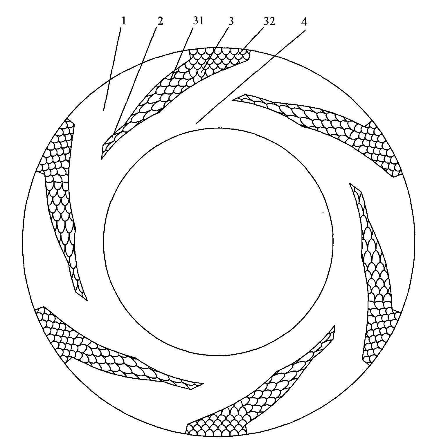
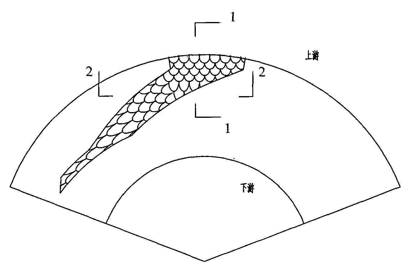
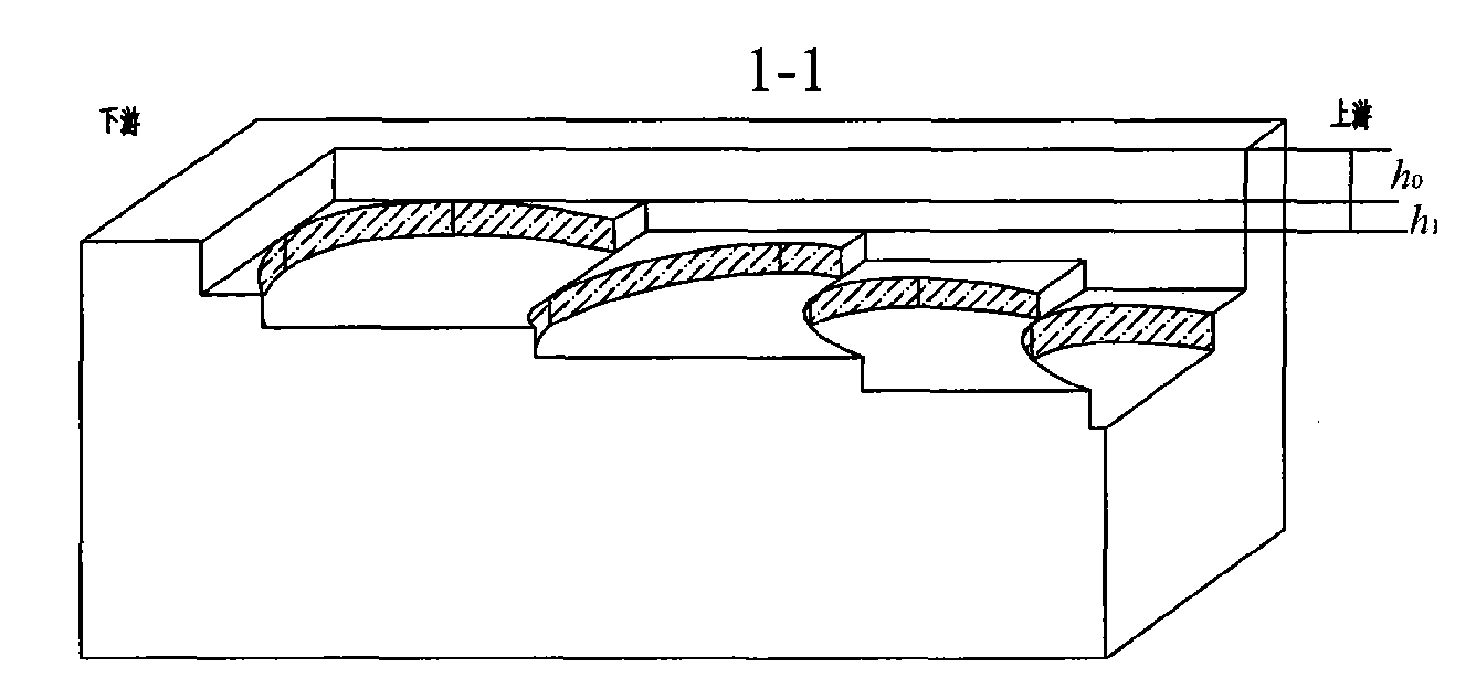
[0027] Reference Figure 1-4 , A three-dimensional feather-like texture bottom surface groove gas end surface sealing structure, including a mechanical end surface seal of a moving ring, a static ring and other related parts. The sealing end surface of the moving ring and the sealing end surface of the static ring are attached to each other to form a circle Annular seal end face, one side of the annular seal end face is the high pressure side, that is, upstream, and the other side of the annular seal end face is the low pressure side, that is, downstream. When rotating, at least one of the sealing end surfaces of the moving ring and the static ring is provided with a plurality of three-dimensional grooves 3 for gas end surface sealing, and the three-dimensional grooves are periodically arranged on the sealing end surface along the ring surface. Distributed symmetrically in the center, the non-slotted area between the three-dimensional grooves constitutes the sealing weir 1. The...

Embodiment 2

[0036] Reference Image 6 The difference between this embodiment and the first embodiment is that the structural dimensions of the spiral groove 31 and the pumping groove 32 are different. The long spiral groove three-dimensional groove and the short spiral groove three-dimensional groove are along the end surface The circumferential direction is distributed periodically, and the groove length and dam length of the short spiral groove three-dimensional groove are larger than l 4 / l 5 The range of values ​​is: l 4 / l 5 =0.8~1.5, the groove shape is shorter and wider, and the groove tail resembles feather texture staggered arrangement; the length ratio of the groove length to the dam length of the long spiral groove three-dimensional groove is l 4 / l 5 The range of values ​​is: l 4 / l 5 =1.5~4.5, the groove shape is relatively narrow, long and flat, and the groove tails are arranged like feather texture parts overlapping; the radial length of the two sides of the pumping groove is d...

Embodiment 3

[0038] Reference Figure 7 , Figure 8 The difference between this embodiment and the first embodiment is that the spiral groove 31 is a bidirectional groove symmetrically distributed along the connection point of the spiral groove 31 with the pumping groove 32. The shape of the spiral groove 31 may be a bird-like wing shape, a crescent shape, a chevron shape, or an iron anchor shape to meet the requirements of bidirectional rotation. The rest of the structure and implementation are the same as the first embodiment.


PUM

PropertyMeasurementUnit
Depthaaaaaaaaaa

Abstract

A gas end surface sealing structure with three-dimensional feather-like textured bottom shaped grooves comprises a dynamic ring and a static ring which are used for sealing a mechanical end surface. As for the dynamic ring and the static ring, at least one sealed end surface is provided with a plurality of three-dimensional shaped grooves. Non-grooved areas among the three-dimensional shaped grooves serve as sealing weirs. Each three-dimensional shaped groove consists of a pumping groove and a spiral groove which are provided with bottoms similar to feather texture features. The pumping grooves are radially distributed and positioned at the upstream part of the sealed end surface. The depths of the pumping grooves are gradually reduced from upstream parts to downstream parts. The pumping groove is connected with the spiral groove. Spiral angles of spiral lines at windward lateral walls of the spiral grooves are greater than the spiral angles of spiral lines at leeward lateral walls. The depths of the spiral grooves are gradually reduced from upstream parts to downstream parts. A continuous planar ring-band sealing dam is arranged at downstream parts of the spiral grooves. The gas end surface sealing structure has the advantages of strong static pressure and dynamic pressure effect of fluid on the end surface, good low-speed start-up performance, excellent pressure resistibility, strong anti-articulation capability, little leakage and good wearability.

Description

Technical field [0001] The invention relates to a gas end face mechanical seal structure of a rotary fluid machine, in particular to a three-dimensional groove gas end face seal structure composed of a pumping groove with a feather-like texture bottom surface and a spiral groove. Type compressor, reactor, pump and other rotary fluid machinery rotating shaft. Background technique [0002] The well-known fluid dynamic pressure or static pressure or combined dynamic and static pressure mechanical end face seals still have some shortcomings, such as spiral groove hydrodynamic end face seals (see Lubrication Engineering, 1990, 46(9): pp607; US patents USA Patent 5702110, 7144016 and 20020093141, world patents WO9506212 and Chinese patents 90101737.X, 96108614.9, 98219179, 01102213.2, 02132978.8 and 02146449.9), the end structure is mainly composed of two parts, namely several spiral grooves evenly distributed along the circumferential direction And the sealing dam closely connected t...

Claims


Application Information

Patent Timeline
IPC IPC(8): F16J15/34
CPCF16J15/3412
Inventor 彭旭东李纪云白少先盛颂恩
Owner ZHEJIANG UNIV OF TECH
Why Eureka
Try Eureka