
Regulating valve for proportioning air and fuel gas

A proportional control valve, gas technology, applied in the direction of diaphragm valve, multi-way valve, safety valve, etc., can solve the problems of non-proportional adjustment, troublesome use, low adjustment accuracy, etc., and achieve the effect of improving the use range

Inactive Publication Date: 2010-02-10
陆守祥
View PDF0 Cites 6 Cited by
  • Summary
  • Abstract
  • Description
  • Claims
  • Application Information

AI Technical Summary

Problems solved by technology

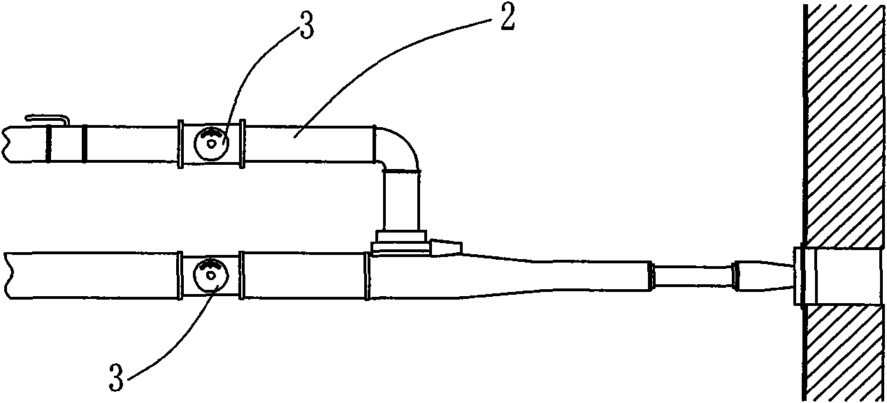
[0002] For existing industrial combustion systems, most of the double butterfly valves are used to adjust the air / gas flow ratio, such as figure 1 As shown, for this kind of combustion system, the butterfly valve 3 on the gas pipeline 2 and the butterfly valve 3 on the air pipeline need to be manually adjusted and controlled separately, which is troublesome to use, and the air and gas flow adjustment cannot be performed simultaneously.
The adjustment response is slow, and the proportional adjustment of air / gas cannot be quickly and effectively achieved, and the work efficiency is low. At the same time, due to the inaccurate manual adjustment accuracy, it cannot be adjusted proportionally, resulting in incomplete combustion of fuel and energy waste.
And because of the low adjustment accuracy, the combustion atmosphere cannot be well controlled during combustion, and defective products are likely to be produced in the furnace chamber that requires an oxygen-deficient atmosphere.
Can not effectively prevent tempering during work, resulting in certain safety hazards

Method used


Image

  • Regulating valve for proportioning air and fuel gas
  • Regulating valve for proportioning air and fuel gas
  • Regulating valve for proportioning air and fuel gas

Examples


Embodiment 1

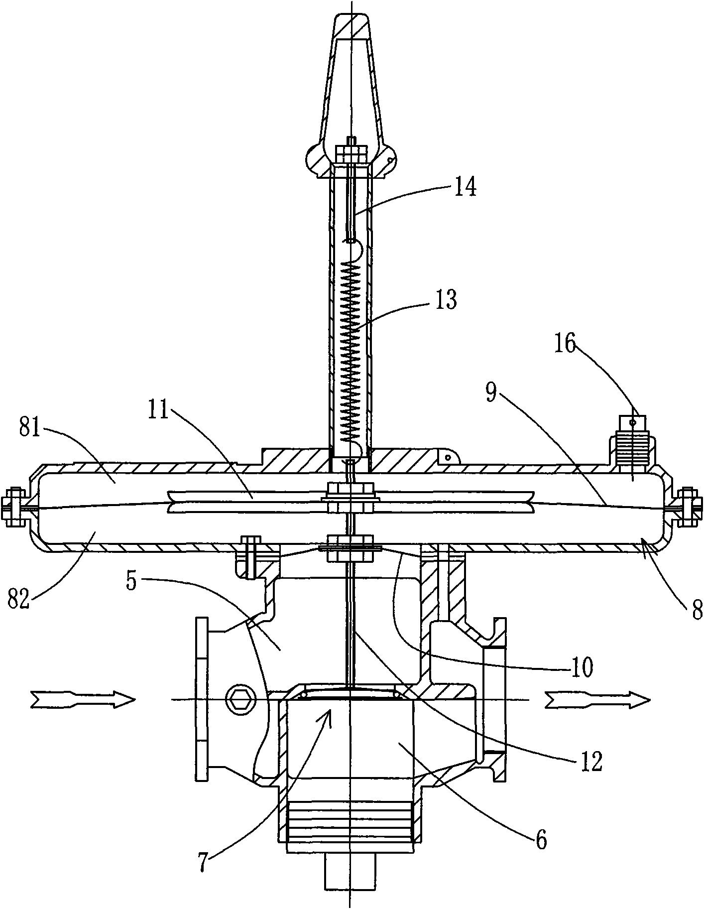
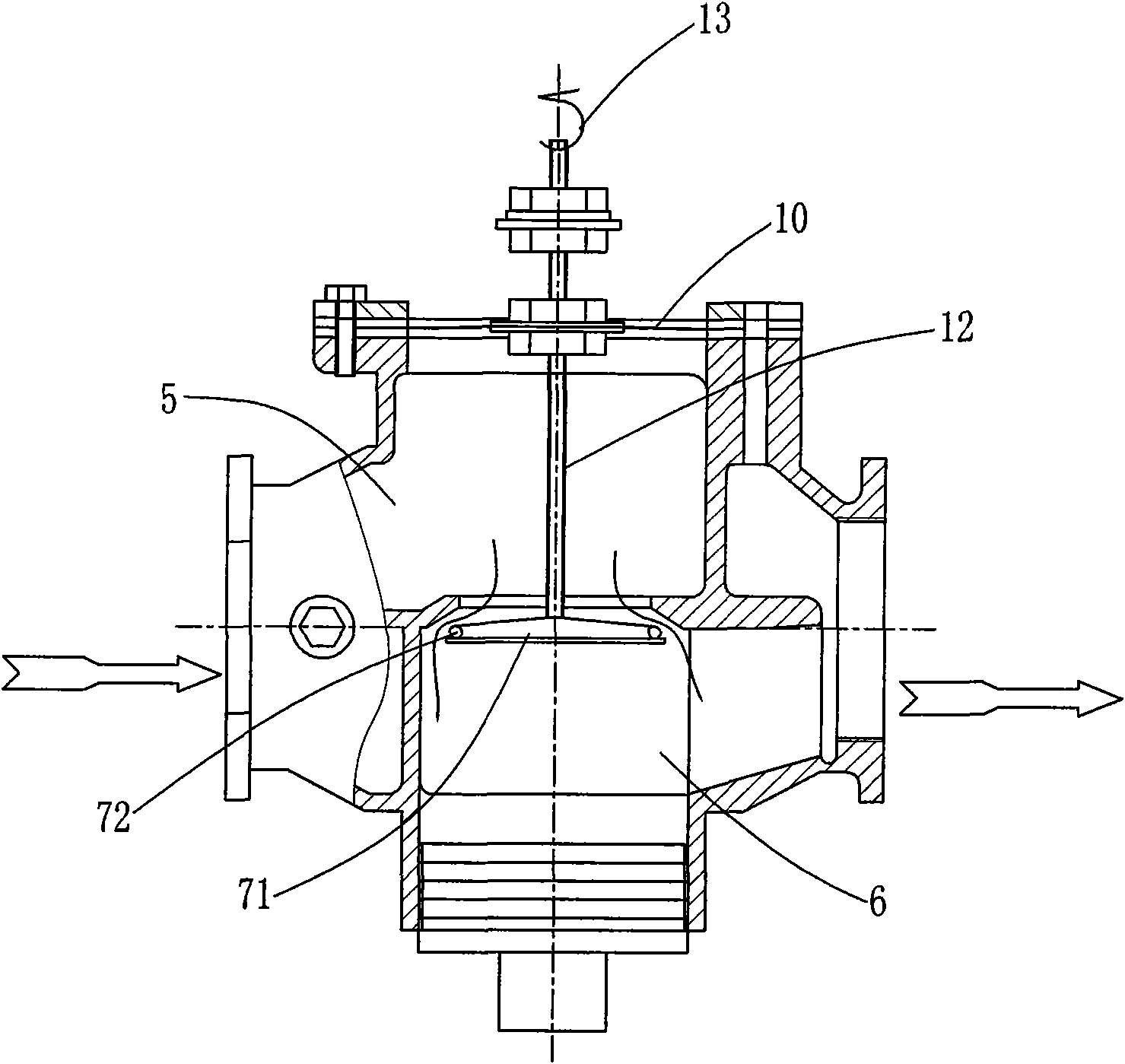
[0025] Example 1: Combining Figure 4 In this embodiment, the regulating valve 1 is installed on the gas pipeline 2, and a butterfly valve 3 is installed on the air pipeline. When the butterfly valve is opened, the combustion-supporting air and the gas are mixed in the suction-type proportional mixer 4, and a negative gas will be generated on the gas pipeline at the outlet end of the regulating valve. pressure, causing the regulating valve to open at the same time. combine figure 2 , 3 , the valve body base of the regulating valve is connected to the gas pipeline 2, and the valve body base has two chambers, that is, the upper chamber 5 connected to the gas inlet, and the lower chamber 6 connected to the gas outlet, and there is a gap between the upper and lower chambers. Valve plate 7, the body of the valve plate is a valve core aluminum disc 71, a valve core sealing ring 72 is sleeved on the outer periphery of the valve core aluminum disc, and the shell wall around the thr...

Embodiment 2

[0029] Example 2, combined with figure 2 , 5 , the regulating valve of this embodiment is also installed on the gas pipeline, and the nozzle mixer 15 will not generate suction to cause negative pressure in the gas pipeline at the outlet end of the regulating valve. The structural difference between this embodiment and the regulating valve in Embodiment 1 is that a feedback hole 16 is opened on the housing of the upper induction chamber 5, and the two ends of the feedback pipe 17 are connected to the feedback hole 16 and the air duct respectively.

[0030] In use, when the butterfly valve 3 on the air pipeline is opened, the combustion-supporting air enters the nozzle mixer 15, and at the same time, the air enters the upper induction chamber 81 of the regulating valve through the feedback pipe 17, and generates downward pressure on the pulse diaphragm 9, and the pulse The diaphragm drives the connecting rod 12 to overcome the tension of the tension spring 13 to go down, and t...


PUM


Abstract

The invention discloses a regulating valve for proportioning air and fuel gas. A valve body seat which is connected on a fuel gas pipeline is provided with two cavities, namely an upper cavity connected with a fuel gas inlet and a lower cavity connected with a fuel gas outlet, and the a valve sheet is arranged between the upper cavity and the lower cavity for opening and closing of the pass of thefuel gas; an airtight induction cavity is arranged in the middle of the valve body, a pulse diaphragm is arranged in the middle of the induction cavity for dividing the induction cavity into an upperinduction cavity and a lower induction cavity which are mutually insolated and excellently sealed, and a sealing diaphragm is arranged between the lower induction cavity and the upper cavity of the valve body seat; a connecting rod is arranged and fixedly connected on the valve sheet vertically, and is fixedly connected with the sealing diaphragm and the pulse diaphragm after vertically penetrating through the sealing diaphragm and the pulse diaphragm; and the top end of the connecting rod is fixedly connected with a tension spring, the top part of which is fixedly connected with a screw rodwhich is thread connected with the shell of the valve body.

Description

Technical field: [0001] The invention relates to a mechanical proportional regulating valve, in particular to an air and gas proportional regulating valve used in industrial combustion equipment and kiln heating systems. Background technique: [0002] For existing industrial combustion systems, most of the double butterfly valves are used to adjust the air / gas flow ratio, such as figure 1 As shown, for this combustion system, the butterfly valve 3 on the gas pipeline 2 and the butterfly valve 3 on the air pipeline need to be manually adjusted and controlled respectively, which is cumbersome to use, and the adjustment of the air and gas flow cannot be carried out synchronously. The adjustment response is slow, and the air / gas ratio adjustment cannot be quickly and effectively achieved. The work efficiency is low. At the same time, due to the inaccurate manual adjustment accuracy, the proportional adjustment cannot be performed, resulting in incomplete combustion of fuel and e...

Claims


Application Information

Patent Timeline
Patent Type & Authority Applications(China)
IPC IPC(8): F16K11/02F16K7/12F16K17/28
Inventor 陆守祥
Owner 陆守祥
Learn More