Automatic calibration system and automatic calibration method for sonic nozzle

A technology of automatic calibration system and sonic nozzle, applied in jet engine testing, gas turbine engine testing, etc., can solve the problems of time-consuming, labor-intensive, low calibration efficiency, etc., to improve safety, save manpower and time, and eliminate manual operation. Effect

Inactive Publication Date: 2010-02-10
BEIHANG UNIV
View PDF0 Cites 21 Cited by
  • Summary
  • Abstract
  • Description
  • Claims
  • Application Information

AI Technical Summary

Problems solved by technology

[0019] figure 2 In the calibration system shown, the pressure reducer 4 must be adjusted for the inlet pressure P of each sonic nozzle. After the adjustment, the solenoid valve 9 is opened and the data is recorded. However, the calibration of a sonic nozzle often needs to observe and record dozens of different The inlet pressure and flow data of figure 2 The system and method shown need to repeat the process of manually adjusting the pressure reducer and switching the valve dozens of ti

Method used


Image

  • Automatic calibration system and automatic calibration method for sonic nozzle
  • Automatic calibration system and automatic calibration method for sonic nozzle
  • Automatic calibration system and automatic calibration method for sonic nozzle

Examples


Embodiment Construction

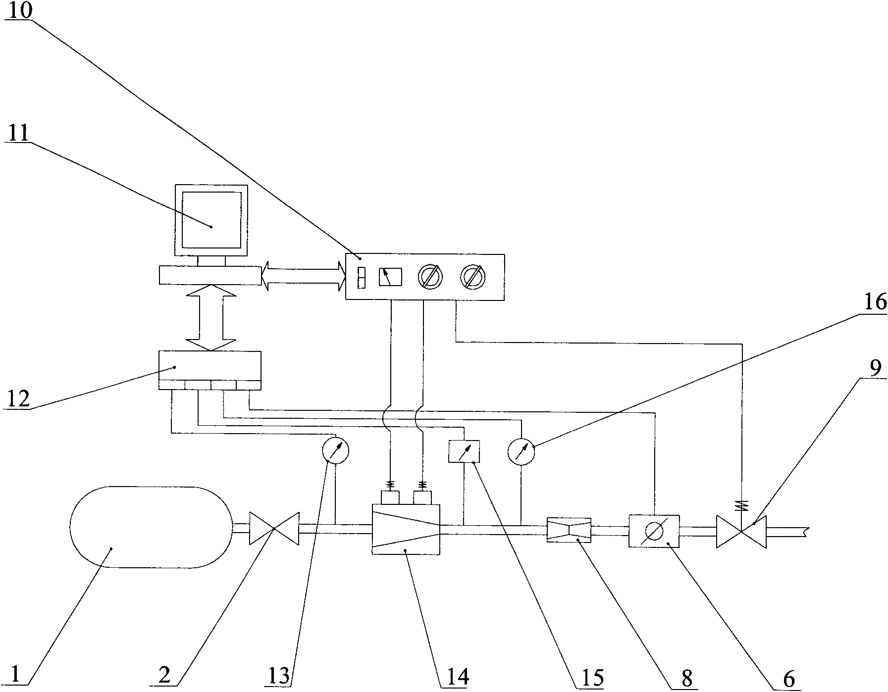
[0030] Sonic nozzle automatic calibration system such as image 3 As shown, clean high-pressure oxygen is stored in the high-pressure gas storage tank 1 as the system gas source. The high-pressure hand valve 2 is the main switch of the air source, and a pressure sensor 13 is arranged downstream of the high-pressure hand valve 2 to detect the pressure of the air source. Quantitative supply type electronically controlled pressure reducer 14 is arranged upstream of the measured sonic nozzle 8, and its function is to change the upstream high-pressure gas into low-pressure gas and send it to the downstream, and its outlet pressure can be adjusted arbitrarily. A temperature sensor 15 and a pressure sensor 16 are arranged upstream of the sonic nozzle 8 to measure the temperature of oxygen and the inlet pressure of the sonic nozzle. The flow meter 6 is arranged downstream of the measured sonic nozzle 8 to measure the flow. Solenoid valve 9 is a system valve. The signals of the pres...


PUM


Abstract

An automatic calibration system and automatic calibration method for sonic nozzle are mainly used for calibrating the flow characteristics of a flow controller (sonic nozzle) in gas propellant feedingsystem of the rocket engine and can improve the manual operation in the traditional calibrating process as automatic operation controlled by a computer. The automatic calibration system for sonic nozzle is formed by connecting an oxygen storage tank, a fixed supply type electrically controlled decompressor, a pressure sensor, a temperature sensor, a measured sonic nozzle, a flowmeter, a control valve, a data collecting device, a valve drive device and a computer in series. An automatic calibrating software is used for driving the fixed supply type electrically controlled decompressor throughthe valve drive device; and the fixed supply type electrically controlled decompressor is used for adjusting the size of the pressure of entrance of the sonic nozzle. The sensor and the data collecting device are used for measuring the parameters of measured sonic nozzle such as entrance pressure and flow rate; and the automatic calibrating software is used for displaying and recording in real time.

Description

【Technical field】 [0001] The invention relates to a propellant conveying system for a ground test of a rocket engine, and is mainly used for calibrating the flow characteristics of a flow controller (sonic nozzle) of a gas propellant. 【Background technique】 [0002] The sonic nozzle is an important part in the gas propellant (such as oxygen, etc.) delivery system, and its function is to control the flow. The structure of the sonic nozzle is as follows figure 1 As shown, it is a Rafal nozzle that contracts first and then expands. The gas propellant flows from left to right, and the section with the smallest flow area is called the throat. The flow control principle of the sonic nozzle can be expressed by the flow formula: [0003] m · = μK P T A - - - ( 1 ) [0004] In the fo...

Claims


Application Information

Patent Timeline
IPC IPC(8): G01M15/14
Inventor 孙冰张佳郑力铭
Owner BEIHANG UNIV
Why Eureka
Try Eureka