Computer-control polishing method based on removal function prediction model

A function model and prediction model technology, applied in electrical program control, surface polishing machine tools, grinding/polishing equipment, etc., can solve problems such as difficulty in ensuring high convergence certainty, reducing processing efficiency, and difficulty in correction.

Active Publication Date: 2010-02-10
NAT UNIV OF DEFENSE TECH
View PDF0 Cites 32 Cited by
  • Summary
  • Abstract
  • Description
  • Claims
  • Application Information

AI Technical Summary

Problems solved by technology

There are two main disadvantages: 1. The accuracy of the efficiency coefficient value between different materials is estimated by experience is low, the correction is difficult, and it is greatly affected by human beings. It is difficult to obtain an accurate removal function mode

Method used


Image

  • Computer-control polishing method based on removal function prediction model
  • Computer-control polishing method based on removal function prediction model
  • Computer-control polishing method based on removal function prediction model

Examples


Embodiment Construction

[0039] The present invention will be further described in detail below in conjunction with specific embodiments and accompanying drawings.

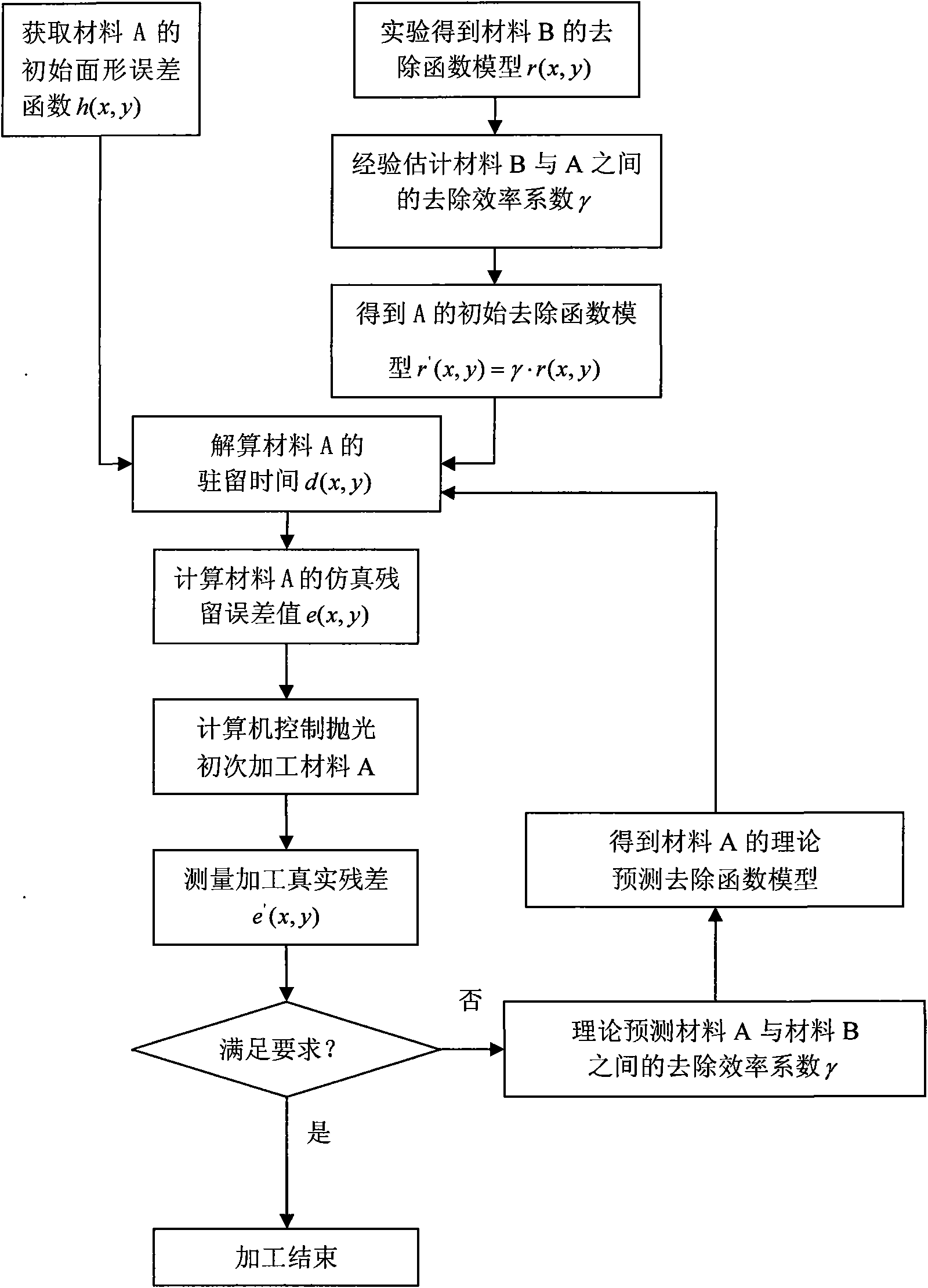
[0040] Such as figure 1 Shown, the present invention is based on the computer-controlled polishing method of removal function prediction model, and its steps are:

[0041] (1) The first computer-controlled polishing of unknown material A through known material B;

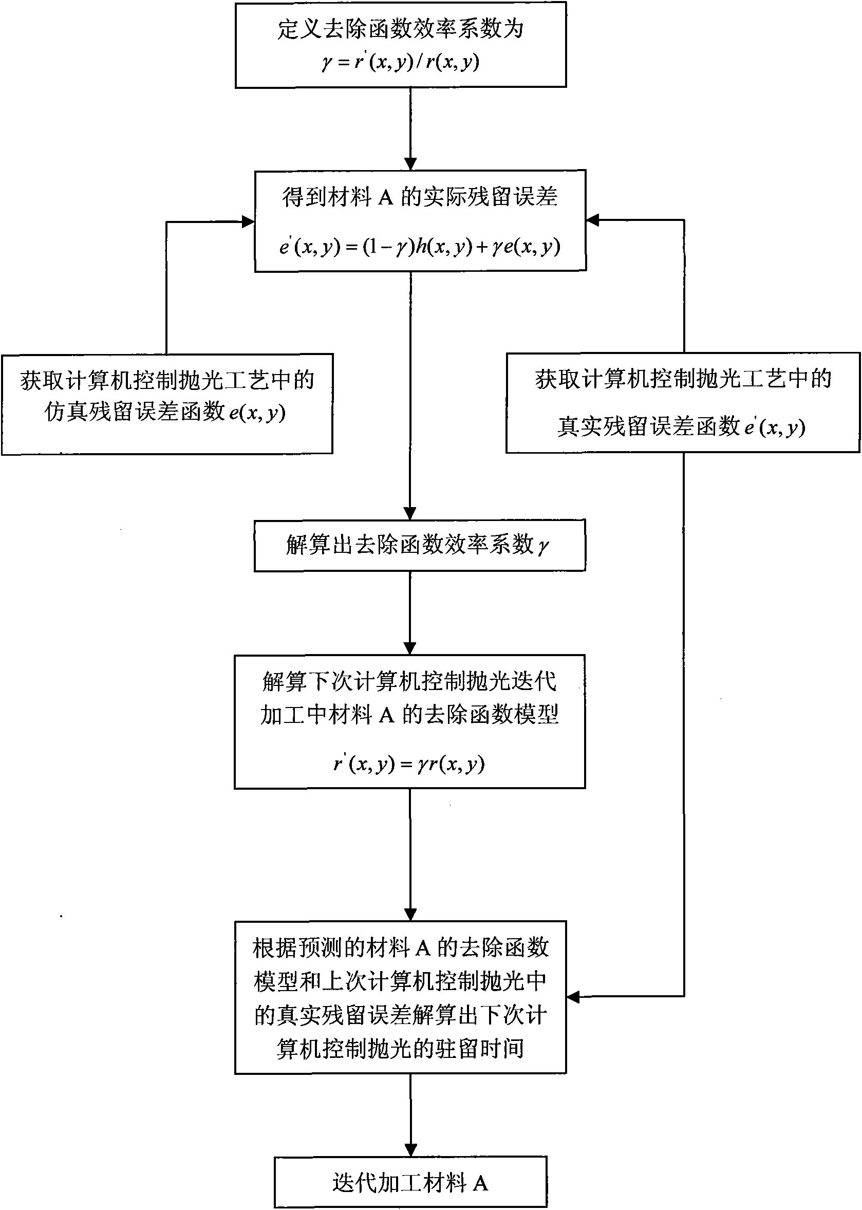
[0042] (2) The removal function model of theoretical prediction material A;

[0043] (3) Based on the predicted removal function model in step (2), the identification of the efficiency coefficient of the removal function model is introduced in the following computer-controlled polishing process. .

[0044] The theoretical basis of material removal in the computer-controlled polishing method is the Preston equation. When the processing parameters are constant, the material removal amount on the surface of the optical part can be expressed as a two-dimensional convolution of t...


PUM


Abstract

The invention discloses a computer-control polishing method based on a removal function prediction model, comprising the following steps: (1) carrying out first computer-control polishing on an unknown material A through a known material B; (2) theoretically predicting the removal function model of the material A; (3) and based on the prediction removal function model in the step (2), introducingan efficiency coefficient identification step in the subsequent computer-control polishing process. The method has the advantages of simple operation, high efficiency, wide application range and highpolishing precision.

Description

technical field [0001] The invention mainly relates to the field of optical processing, in particular to a computer-controlled polishing method based on a removal function prediction model. Background technique [0002] Computer-controlled polishing technology is a new type of optical processing technology developed in the 1970s. Its traditional concept is mainly aimed at computer-controlled small tool polishing technology, mainly using a polishing disc that is much smaller than the workpiece. Under this condition, it moves on the surface of the optical part with a specific path and speed, and by controlling the residence time and processing pressure in each area, the removal amount of the part material can be precisely controlled to achieve the purpose of correcting errors and improving precision. The outstanding advantage of this technology is that the small tool can effectively track the change of the radius of curvature of each point on the aspheric surface during proces...

Claims


Application Information

Patent Timeline
IPC IPC(8): G05B19/04B24B29/00
Inventor 戴一帆李圣怡彭小强宋辞谢超
Owner NAT UNIV OF DEFENSE TECH
Why Eureka
Try Eureka