Novel rotating miller

A rotary milling machine, a new type of technology, applied in milling machine equipment, milling machine equipment details, large fixed members, etc., can solve the problems of high processing cost, increased workload, slow turning speed, etc., to achieve convenient installation and positioning, avoid potential safety hazards, guarantee The effect of parallelism

Inactive Publication Date: 2010-02-17
NANTONG ZHENHUA HEAVY EQUIP MFG
View PDF0 Cites 12 Cited by
  • Summary
  • Abstract
  • Description
  • Claims
  • Application Information

AI Technical Summary

Problems solved by technology

The structure is heavy, the rotational inertia is large, and the turning speed is slow, resulting in waste of energy and high processing costs
[0004] 2. The vertical lathe cannot process the lower track surface supported by the slewing crane, and cannot process the upper and lower track surfaces at the same time after one positioning;
[0005] 3. The vertical lathe equipment needs to clamp the lower support of the slewing on the workbench, so that it needs to be transferred and clamped reliably, which increases the workload and has potential safety hazards

Method used


Image

  • Novel rotating miller

Examples


Embodiment approach

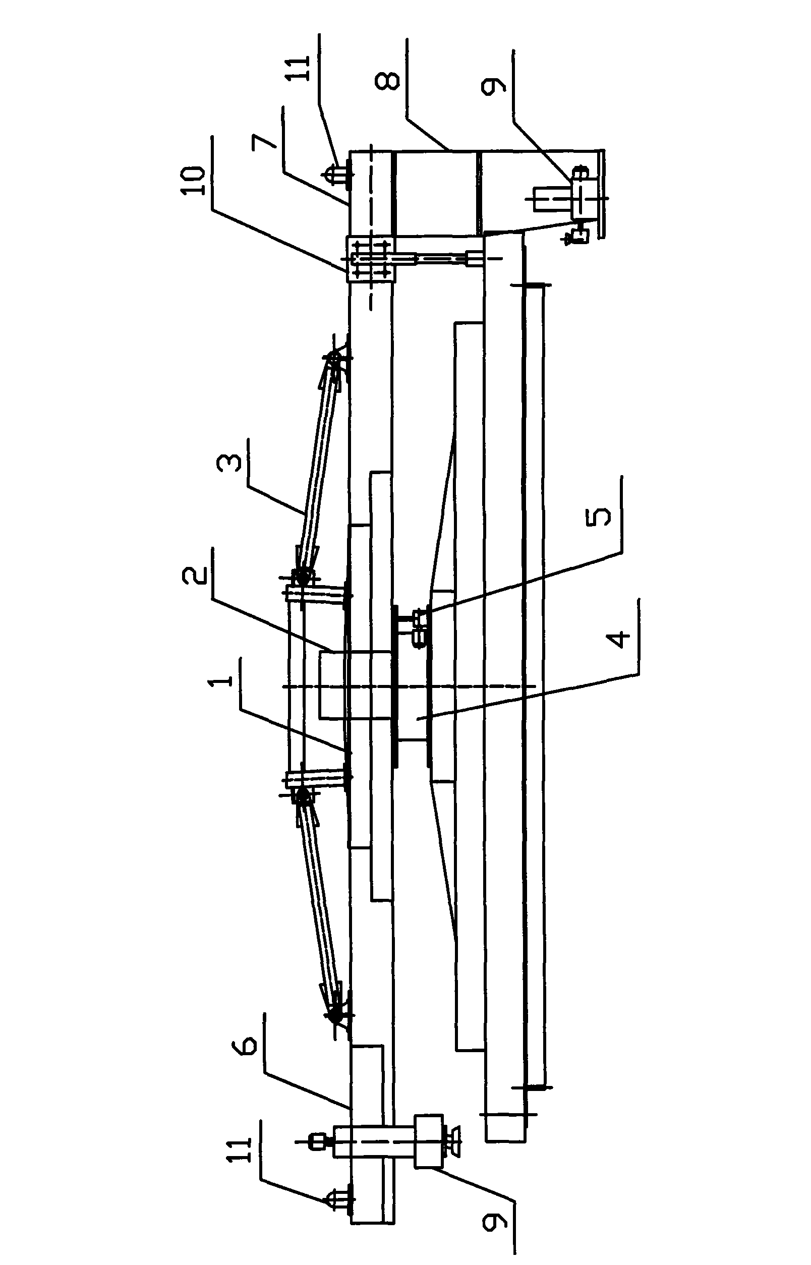
[0022] Such as figure 1 It shows an embodiment of the present invention, a rotary milling machine, including a main beam 1, the main beam 1 is connected with an electrical cabinet 2 provided, a tie rod mechanism 3 is arranged above the main beam 1, and a A workbench 4 is provided below, and a rotary mechanism 5 is provided on the side of the lower end of the workbench 4. The left and right ends of the main beam 1 are provided with a left beam 6 and a right beam 7, and the right beam 7 is connected with a longitudinal beam 8 arranged vertically. , the left beam 6 is connected with a power cutting head 9, the right beam 7 is also connected with a power cutting head 9 through the longitudinal beam 8, and a support structure 10 is provided on the side of the junction between the main beam 1 and the right beam 7, and the support structure 10 is rigid The wheel can adjust the deflection of the main beam 1 up and down. There are warning lights 11 on the left beam 6 and the right beam...


PUM


Abstract

The invention discloses a novel rotating miller which comprises a main beam that is connected with an electric appliance cabinet; a drag link mechanism is arranged above the main beam, a workbench isarranged below the main beam, a rotating mechanism is arranged at the lower end of the workbench, and a left beam and a right beam are arranged at the left end and the right end of the main beam, wherein the right beam is connected with a longitudinal beam, the left beam and the right beam are connected to a power cutting head, a support structure is arranged at the side of the connection part ofthe main beam and the right beam, and alarm lamps are arranged at two ends of the main beam. The invention has good security, small volume, convenient installation and gas milling speed and can achieve the advantages that two annular orbit planes are processed simultaneously after once positioning, and the parallelism degree is high after being processed.

Description

Technical field: [0001] The invention relates to a processing machine for marine engineering machinery, in particular to a new type of rotary milling machine specially used for large-scale steel structure circular plane processing. Background technique: [0002] From the perspective of the industry, at present, the lower support of the floating crane is divided into upper and lower track planes, and the requirements for parallelism and flatness of the two planes are relatively high. The lower supporting member of the slewing is a welded steel structure, and the flatness of the track surface after welding is poor. In order to have a higher flatness, the method of machining the track surface with a margin is used to ensure it. However, the existing large-scale vertical lathes for processing the supporting plane under the slewing of floating cranes mainly have the following deficiencies: [0003] 1. The processing cycle is long, and the level of the support under the rotation ...

Claims


Application Information

Patent Timeline
Patent Type & Authority Applications(China)
IPC IPC(8): B23C3/02B23Q1/25B23Q1/01
Inventor 魏炳宁沈卫军鞠小刚
Owner NANTONG ZHENHUA HEAVY EQUIP MFG
Why Eureka
Try Eureka