Piston compressor and refrigerant compressor

一种压缩机、制冷剂的技术,应用在机器/发动机、机械设备、液体变容式机械等方向,能够解决压缩机应用性能降低、效率降低等问题

Inactive Publication Date: 2010-02-17
DANFOSS AS
View PDF2 Cites 0 Cited by
  • Summary
  • Abstract
  • Description
  • Claims
  • Application Information

AI Technical Summary

Problems solved by technology

However, in general, low manufacturing costs run the risk of reduced application performance of the compressor
In particular, there is a risk of reduced efficiency

Method used


Image

  • Piston compressor and refrigerant compressor
  • Piston compressor and refrigerant compressor
  • Piston compressor and refrigerant compressor

Examples


Embodiment Construction

[0021] figure 1 is a schematic diagram of a refrigerant compressor 1 having a compression chamber 2 formed in a cylinder 3 . The cylinder 3 is located in the compressor block 4 . The volume of the compression chamber 2 can be changed by the piston 5, and the driver (not shown in detail) drives the piston 5 to reciprocate through the connecting rod 6.

[0022] The cylinder block 4 is located in a suction passage 7 through which refrigerant gas is sucked into the compression chamber 2 . A compression channel 8 leads partly through the compressor block 4 and supplies compressed refrigerant gas to a compressed gas collection 9 .

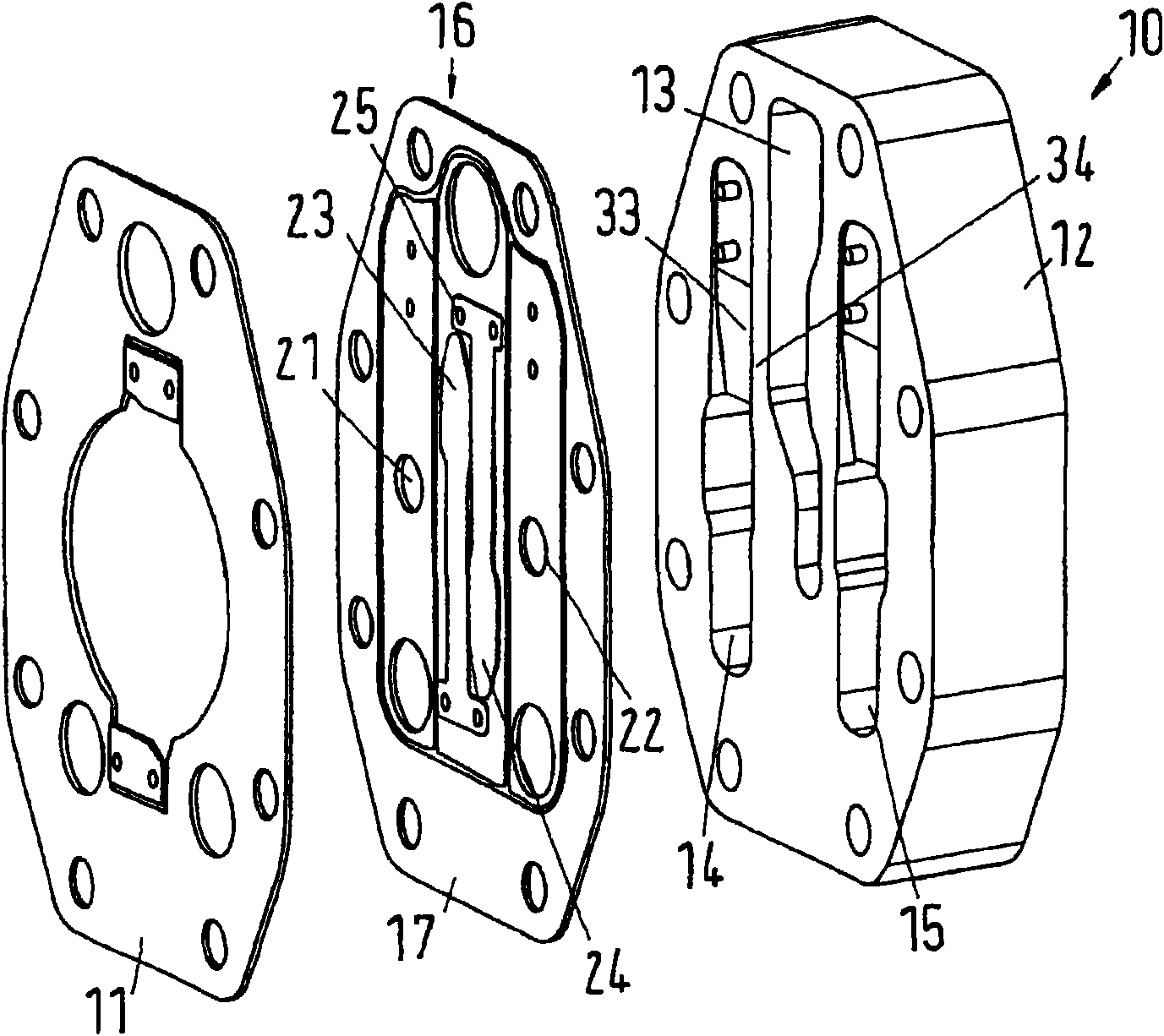
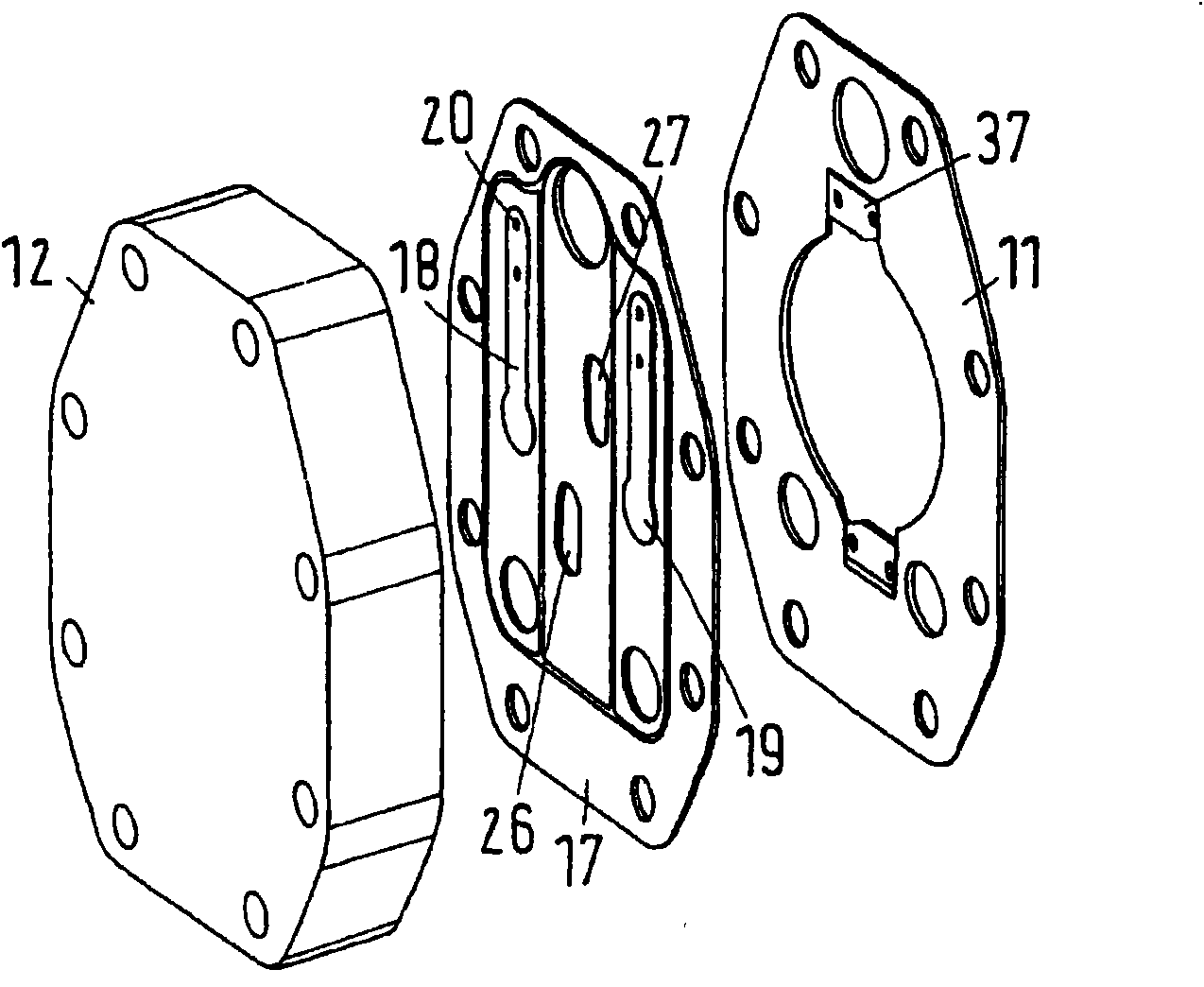
[0023] The cylinder head 10 closes the compression chamber 2 on the front side of the cylinder 3 . The seal 11 is located between the cylinder head 10 and the compressor block 4 . Below, through Figures 2 to 5 The cylinder head 10 is explained in detail.

[0024] The cylinder head 10 has a valve cover 12 in which a suction gas channel 13 and two c...


PUM


Abstract

The invention relates to a piston compressor, especially a refrigerant compressor, which has a compression chamber arranged in a compressor block and limited by a cylinder head (10), the cylinder headhas at least one suction valve (23, 24) and at least one pressure valve (21, 22) as well as at least one plate valve arrangement of a valve cover (12). The invention intends to realize low manufacture cost, and good efficiency. Therefore, the valve plate arrangement (16) is formed by a support plate (17) comprising suction valves (23, 24, 26, 27) and pressure valves (18, 19, 21, 22), and the support plate (17) is connected to the valve cover (12) by at least one airtight connecting seam (28, 31), a suction area (22) and a compression area (32) are separated each other by the connecting seam (28, 31), and at least the compression area (29, 30) is sealed relatively to the outside.

Description

technical field [0001] The invention relates to a piston compressor, in particular a refrigerant compressor, having a compression chamber in the compressor body, said compression chamber being defined by a cylinder head comprising a cylinder having at least one The valve plate structure of the suction valve and at least one pressure valve and a valve cover. Background technique [0002] Such a piston compressor is known, for example, from DE 10 2004 047 159 B4. The valve plate structure includes a pressure valve plate and a suction valve plate. The pressure valve plate and the suction valve plate are connected to each other and to the valve cover by welding. The pressure valve plate has several pressure valve elements which are part of the pressure valve plate. Similarly, the suction valve plate has several suction valve elements as part of the suction valve plate. [0003] DE 10330760 B4 shows another piston compressor, in which, in addition to the pressure valve plate ...

Claims


Application Information

Patent Timeline
Patent Type & Authority Applications(China)
IPC IPC(8): F04B39/00F04B39/10
CPCF04B39/1073Y10T137/7892Y10T137/6086
Inventor 于尔根·萨斯克里斯琴·杰普森
Owner DANFOSS AS
Why Eureka
Try Eureka