

Automatic temperature control LED hose lamp
A technology of LED hose lights and automatic temperature control, which is applied to the layout of electric light circuits, damage prevention measures for lighting devices, lighting and heating equipment, etc. It can solve problems such as irreparable, safety hazards, poor heat dissipation, etc., and achieve good white balance effect, the effect of meeting the heat dissipation needs
- Summary
- Abstract
- Description
- Claims
- Application Information
AI Technical Summary
Problems solved by technology
Method used
Image

Examples
Embodiment 1
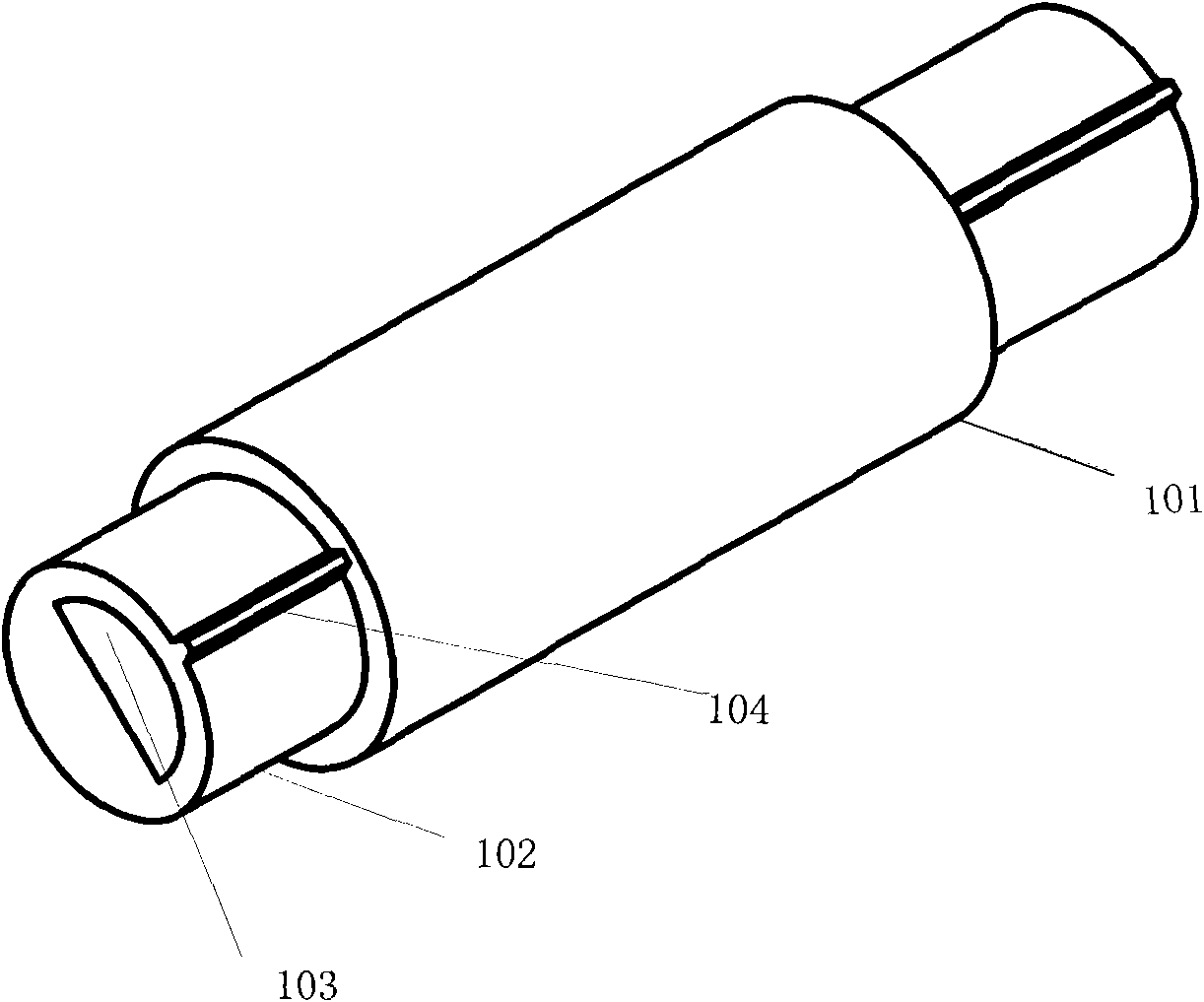
[0038] like figure 1 and figure 2 As shown, an automatic temperature-controlled LED hose lamp includes a light-transmitting lamp tube 101, a flexible inner intestine 102, a lamp body 105 and an automatic temperature control circuit 100; the light-transmitting lamp tube 101 and the flexible inner intestine can be made of thermoplastic flame retardant Insulating plastic PVC, the light-transmitting light tube 101 is tightly wrapped outside the flexible inner intestine 102, and a cavity 103 is arranged inside the flexible inner intestine 102. In this embodiment, the shape of the cavity is a semicircle, and it can also be other shapes such as rectangle, triangle, etc. , the lamp body 105 is placed inside the cavity 103 of the flexible inner intestine 102, and the lamp body includes: a flexible PCB board, an LED light-emitting unit arranged on the flexible PCB board, and a chip arranged on the flexible PCB board to control the light-emitting of the LED light-emitting unit; The LED...
Embodiment 2
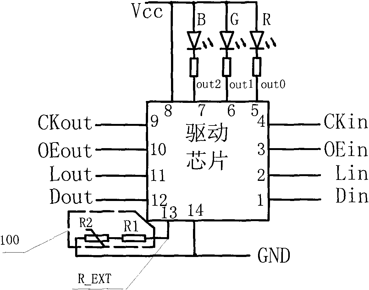
[0044] like figure 2 Shown is a circuit structure of the automatic temperature control hose lamp in the application. The driver chip adopts a constant current driver chip with three driving output terminals OUT1, OUT2 and OUT3. The 13 pin of the chip is the external resistor input terminal R_EXT. Adjust the output current of the constant current output terminals OUT1, OUT2 and OUT3 through the resistance value of the resistor connected to this pin, the formula is I OUT =V R_EXT / (R1+R2), where V R_EXTis the voltage of the R_EXT pin, R1 is the resistance value of the current limiting resistor, R2 is the resistance value of the thermistor, and the LED light-emitting unit consists of a red light-emitting diode R, a green light-emitting diode G, a blue light-emitting diode B and resistors R1, It is composed of R2 and R3, and the LED lights are connected in series with R1, R2, and R3 respectively; the power supply positive line VCC and the power supply negative line GND provide ...
Embodiment 3
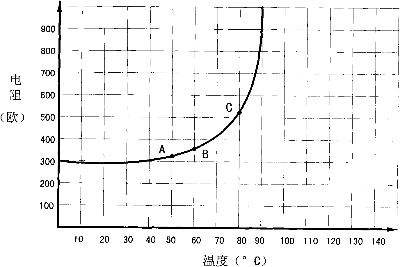
[0046] On the basis of the above embodiments, this embodiment preferably adopts a positive temperature coefficient (PTC, positive temperature coefficient) thermistor R2, such as image 3 Shown is the resistance-temperature curve of the positive temperature coefficient thermistor. Since the optimal operating temperature of the LED lamp and LED driver chip is 50°C to 80°C (as shown by points A and C in the figure), higher than At 80℃, there is a risk of damage. Therefore, the temperature must be controlled before the temperature rises to 80℃. Therefore, it is preferred to use a Curie point of 50℃ to 80℃, and the best is 60℃ (as shown by point B in the figure). shown) PTC thermistor.
[0047] A type of positive temperature coefficient thermistor, the resistance value of the positive temperature coefficient thermistor shows a step increase with the increase of the temperature of the PTC thermistor body. The higher the temperature, the greater the resistance value. The PTC thermis...
PUM
 Abstract
Description
Claims
Application Information