Laser beam axis sight deflection test system under external field environment

An optical system and optical axis technology, which is applied in the direction of measuring devices, optical devices, instruments, etc., can solve the problems of poor working accuracy of precision testing devices for photoelectric aiming equipment, achieve overall size reduction, improve signal-to-noise ratio, and improve detection effect of distance

Inactive Publication Date: 2010-02-17
XIAN TECHNOLOGICAL UNIV
View PDF0 Cites 6 Cited by
  • Summary
  • Abstract
  • Description
  • Claims
  • Application Information

AI Technical Summary

Problems solved by technology

[0007] The present invention provides a laser optical axis aiming deviation test system in an external field environment to overcome the problem o

Method used


Image

  • Laser beam axis sight deflection test system under external field environment
  • Laser beam axis sight deflection test system under external field environment

Examples


Embodiment Construction

[0015] The present invention will be described in detail below in conjunction with the accompanying drawings and embodiments.

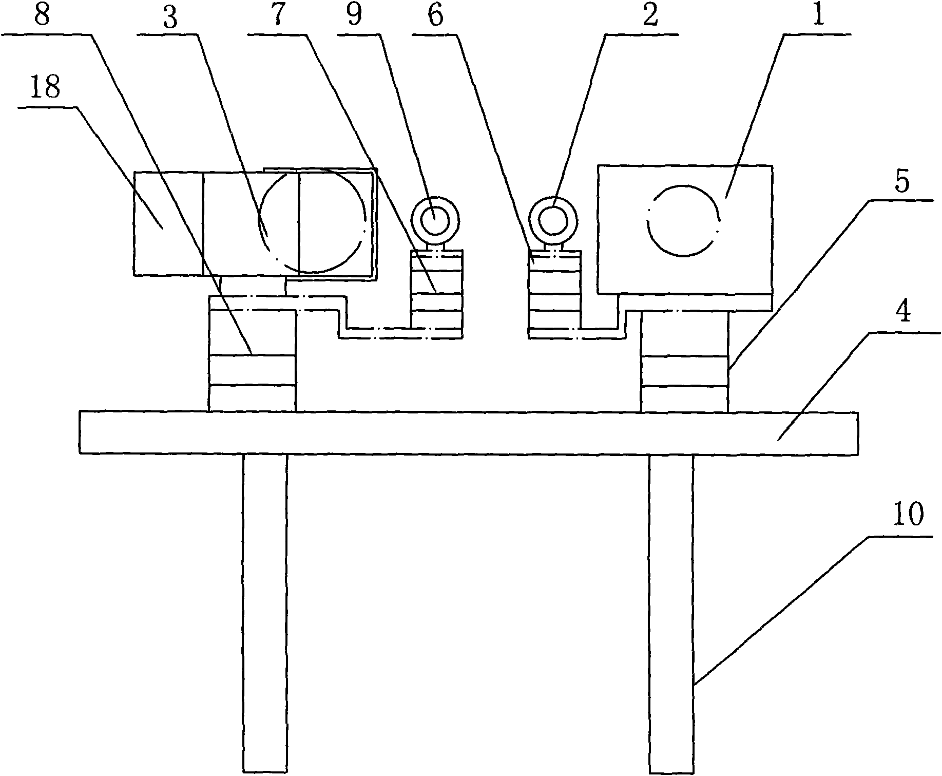
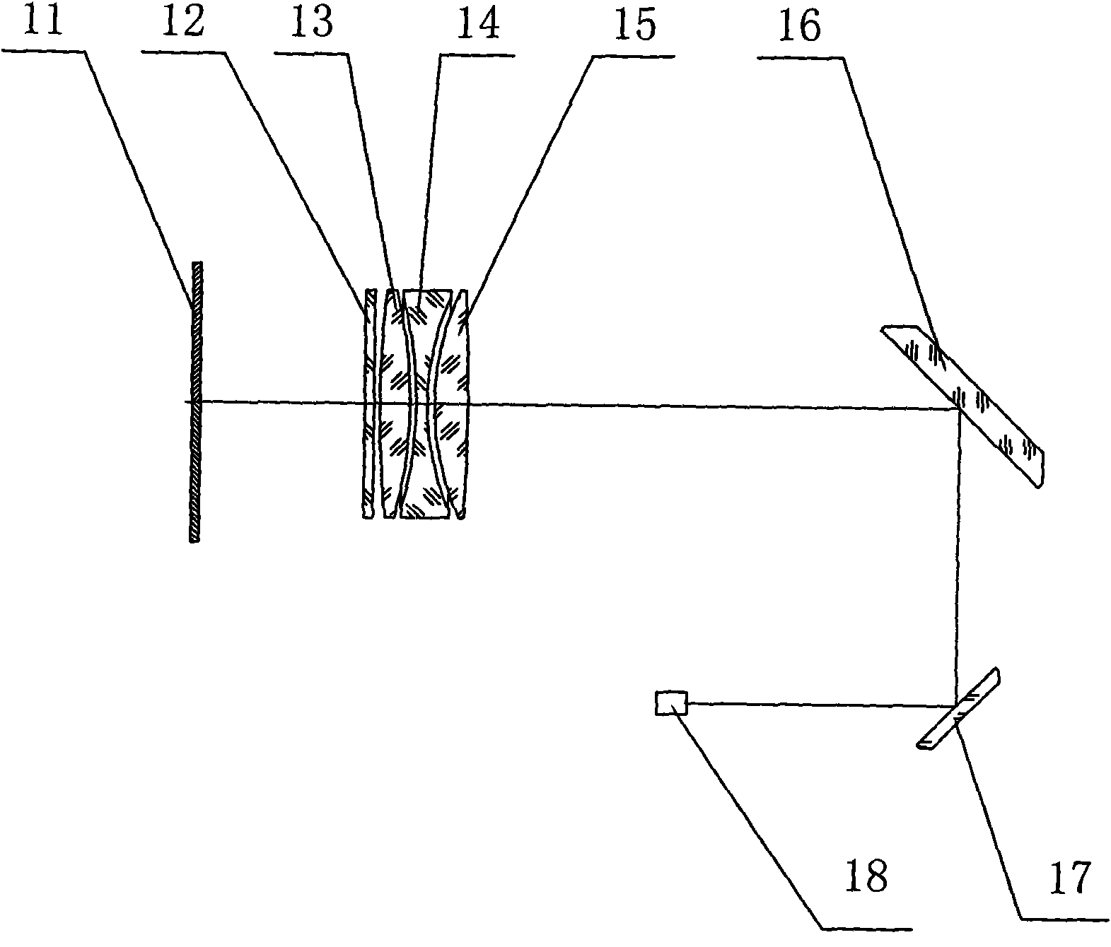
[0016] see Figure 1~2 , a laser optical axis aiming deviation test system in an external environment, including a launch mechanism, an adjustment mechanism and a receiving assembly, the launch mechanism includes a first sight glass 2 and a laser 1 arranged on the adjustment mechanism, and the adjustment mechanism includes a set The laser device adjustment mechanism 5 on the optical platform 4, the first scope adjustment mechanism 6, the second scope adjustment mechanism 7 and the laser receiving objective lens adjustment mechanism 8; the receiving assembly includes the second scope 9, laser Receiving optical system and CCD18, described second sight glass 9 is arranged on the second sight glass adjusting mechanism 7, laser receiving optical system is made up of optical filter 12, objective lens first lens 13, objective lens second lens 14, objective l...


PUM


Abstract

The invention relates to the technical field of optical equipment, specifically relating to the technical field of sight deflection test devices, in particular to a laser beam axis sight deflection test system under external field environment. In order to overcome the problem of poor working accuracy of photoelectrical sight device and precise test devices under external field environment in the prior art, the invention adopts the following technical scheme: the laser beam axis sight deflection test system under external field environment comprises a fire mechanism, an adjusting mechanism anda receiving component, wherein, the fire mechanism comprises a first sight lens and a laser; the adjusting mechanism comprises a laser adjusting mechanism, a first sight lens adjusting mechanism, a second sight lens adjusting mechanism and a laser receiving objective lens adjusting mechanism; and the receiving component comprises a second sight lens, a laser receiving optical system and a CCD. Compared with the prior art, the invention has the advantages of high accuracy and good effect.

Description

Technical field: [0001] The invention relates to the technical field of optical equipment, in particular to the technical field of aiming deviation testing devices, in particular to a laser optical axis aiming deviation testing system in an external field environment. Background technique: [0002] Whether the laser and visible light can accurately aim at the target in the precision test system depends on the aiming consistency of the optical axes of the two bands of the system. If the aiming consistency deviation is large, the test error will become larger. The existing photoelectric aiming equipment and the two optical axis systems in the precision testing device can be guaranteed to be basically parallel after precise adjustment in the laboratory. Most of the photoelectric aiming equipment and precision testing devices in China use reflective two-meter collimator to calibrate and test the two optical axes in the laboratory. [0003] Since the actual work of the device un...

Claims


Application Information

Patent Timeline
IPC IPC(8): G01B11/27
Inventor 高明吴振森倪晋平侯宏录杜玉军李建超马卫红吕宏王青松
Owner XIAN TECHNOLOGICAL UNIV
Why Eureka
Try Eureka