Check patentability & draft patents in minutes with Patsnap Eureka AI!

Method for detecting lubricating terminal of intermittent guide rail and lubricating device using same

A lubricating device, intermittent technology, applied in the direction of measuring device, engine lubrication, quantitative device, etc., can solve the problems of low oil supply pressure, no oil damage on the guide rail, and failure to find the problem of metering components, etc.

Active Publication Date: 2011-08-10
BEIJING NO 2 MACHINE TOOL WORKS
View PDF0 Cites 0 Cited by
  • Summary
  • Abstract
  • Description
  • Claims
  • Application Information

AI Technical Summary

Problems solved by technology

[0004] First, all kinds of metering elements are generally very precise and have small holes, which cannot be found in case of blockage or valve stem stuck and failure, because the pressure relay only detects whether there is oil supply at the front end of the metering element instead of detecting its output end, so problems with the metering element itself cannot be found
[0005] Second, if the oil supply pipeline of the metering element or the guide rail is broken or blocked, it cannot be found when the oil supply to the guide rail cannot be normal
Due to the above problems, the phenomenon of oil-free grinding of the guide rail occurs from time to time, and the losses caused by it can be imagined
[0006] Third, the oil supply pressure actually required by the guide rail is usually relatively low, generally less than 0.05MPa, and in order to pursue a small volume of the metering element, the oil supply pressure at the front end must reach 2.0MPa, thus causing a waste of energy

Method used


Image

  • Method for detecting lubricating terminal of intermittent guide rail and lubricating device using same
  • Method for detecting lubricating terminal of intermittent guide rail and lubricating device using same
  • Method for detecting lubricating terminal of intermittent guide rail and lubricating device using same

Examples


Embodiment Construction

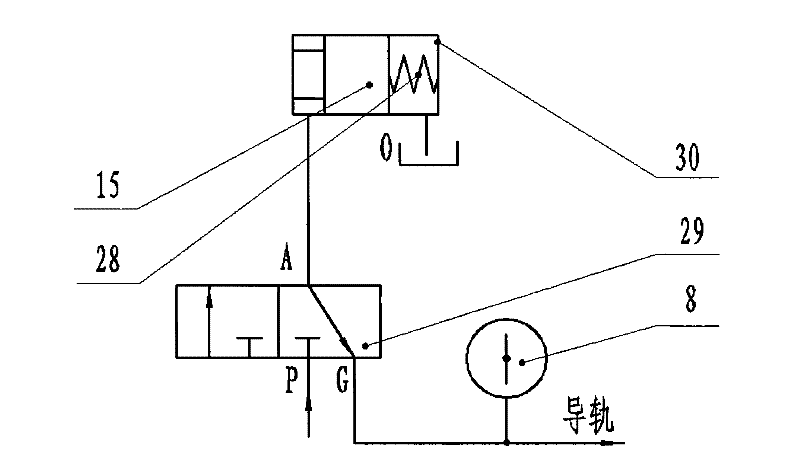
[0030] The terminal detection method of the intermittent guide rail lubrication of the present invention can perform terminal detection because it utilizes the pressure peak caused by sudden oil supply during the guide rail lubrication process and the pressure gradually decreases due to the gradual discharge of oil to the guide rail. The characteristic is that a pressure detection element for monitoring the pressure change of the output end is installed at the output end of the lubricating device connected with the oil pipe of the lubricating terminal, such as an electric contact pressure gauge. The pressure detection element can convert the voltage value into an electrical signal and output it to a corresponding control system for joint control with other actions. In addition to a visual pointer similar to ordinary pressure gauges, the electric contact pressure gauge also has two adjustable pointers, which can respectively send signals for the high pressure and low pressure co...


PUM


Abstract

The invention relates to a method for detecting a lubricating terminal of an intermittent guide rail used in a machine tool and a lubricating device using the method. In the method, a pressure detecting element is arranged in an oil supply system; a parameter relating to the pressure and detected by the pressure detecting element is compared with the corresponding parameter in the state of normaloil supply so as to judge whether the oil supply system in the front and back of the pressure detecting element is normal or not. An output end of the device is provided with the pressure detecting element for monitoring the pressure of the output end; and a metering valve that is used for controlling the oil supply to a lubricating terminal as well as an oil charge unit that is used for controlling the operation of the metering valve are integrated into the same valve body. The invention can effectively detect the oil supply condition at the lubricating terminal, has the advantages of compact structure, high reliability and low pressure of the needed oil sources and can realize stepless presetting of oil supply pressure and oil supply. The invention is mainly used for lubricating orbits of the machine tool and other intermittent oil supply occasions.

Description

technical field [0001] The invention relates to a terminal detection method mainly used for intermittent lubrication of machine tool guide rails, screw screws, etc. and a lubrication device using the method, in particular to a kind of oil supply pressure and oil supply volume that can be adjusted steplessly in advance, and The intermittent lubrication method and device thereof can truly realize the detection of the lubrication terminal during the lubrication process. Background technique [0002] As we all know, all kinds of sliding guides and even some rolling guides need to be lubricated with thin oil in order to reduce friction and prolong service life. In order to save lubricating oil, in many occasions, regular and quantitative intermittent oil supply is used to achieve lubrication. At this time, basically such as figure 1 In the guide rail lubricating device shown, the small oil tank 1 is equipped with a quantitative oil pump, a motor, and an overflow valve. When the ...

Claims


Application Information

Patent Timeline
Patent Type & Authority Patents(China)
IPC IPC(8): G01L9/00B23Q11/12F16N7/38F16N27/00
Inventor 刘德鉁穆东辉李伟华王波苏洪涛
Owner BEIJING NO 2 MACHINE TOOL WORKS
Features
  • R&D
  • Intellectual Property
  • Life Sciences
  • Materials
  • Tech Scout
  • Unparalleled Data Quality
  • Higher Quality Content
  • 60% Fewer Hallucinations
Learn More