Light conducting plate

A technology of light guide plate and resin plate, which is applied in the field of light guide plate and can solve problems such as inability to process well

Active Publication Date: 2010-02-17
SUMITOMO CHEM CO LTD
View PDF9 Cites 7 Cited by
  • Summary
  • Abstract
  • Description
  • Claims
  • Application Information

AI Technical Summary

Problems solved by technology

Conventionally, light guide plates have been manufactured by injection molding (for example, refer to Patent Doc

Method used


Image

  • Light conducting plate
  • Light conducting plate
  • Light conducting plate

Examples


Embodiment 1~6、8 and comparative example 1~4

[0146]

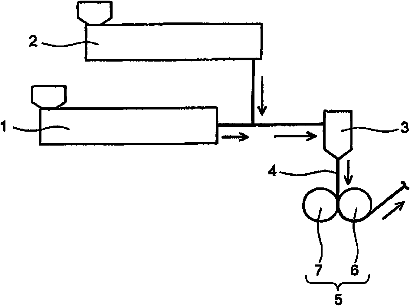
[0147] The resins of the types shown in Table 1 were melt-kneaded with the extruder 1 and supplied in the order of the feed block and the die 3 . Next, the molten thermoplastic resin 4 extruded from the die 3 was formed into a film while being sandwiched between the first roll and the second roll constituted by the rolls shown in Table 1, and an extruded resin sheet having the thickness shown in Table 1 was obtained. In addition, the "1st roll surface temperature" and "2nd roll surface temperature" in Table 1 are the values ​​of the actual roll surface temperature.

Embodiment 7

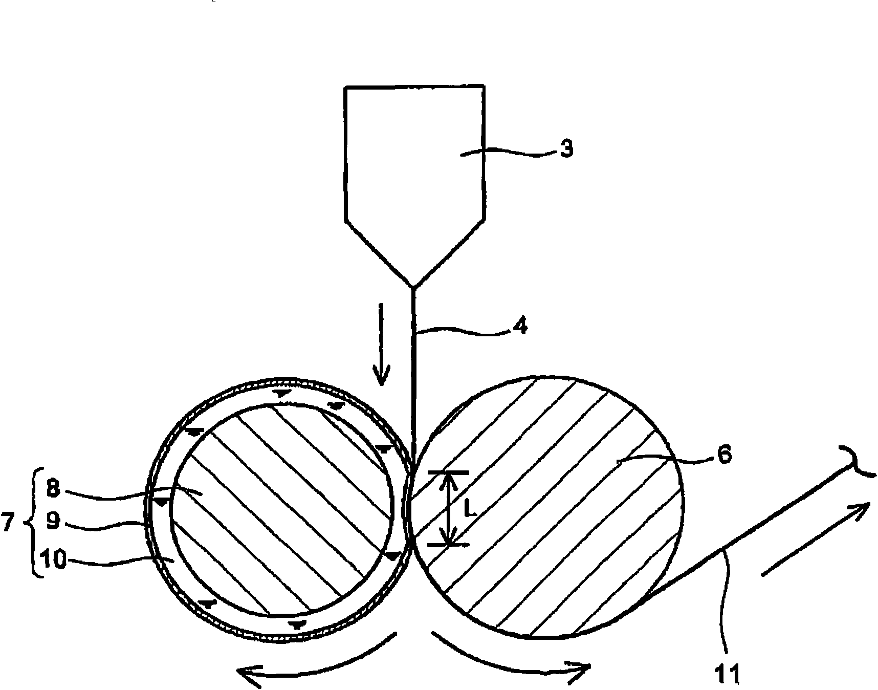
[0149] As the resin layer A, resins of the types shown in Table 1 were melt-kneaded with the extruder 1 and supplied to the feed block. On the other hand, as the resin layer B, resins of the types shown in Table 1 were melt-kneaded with the extruder 2 and supplied to the feed block. Coextrusion molding is performed in such a way that the resin layer A supplied to the feed block from the extruder 1 becomes the main layer, and the resin layer B supplied to the feed block from the extruder 2 becomes the surface layer (one side / upper side) .

[0150] Next, while the molten thermoplastic resin 4 extruded from the die 3 was sandwiched between the first roll and the second roll constituted by the rolls shown in Table 1, a film was formed so that the resin layer B was in contact with the second roll, An extruded resin sheet having a two-layer structure having the thickness shown in Table 1 was obtained. In addition, "thickness" in extruder 1, 2 in Table 1 shows each thickness of res...

Embodiment 9 and comparative example 5

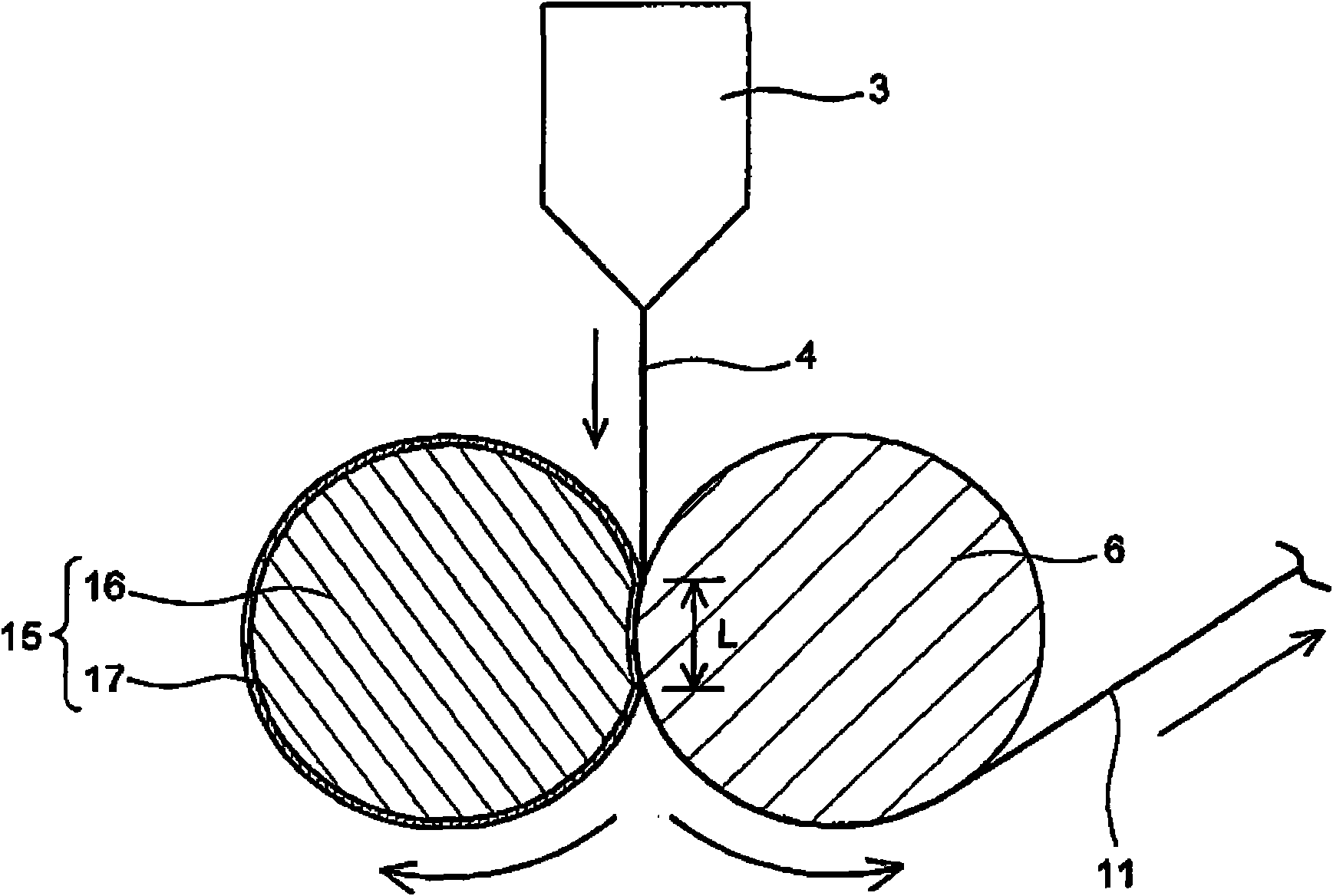
[0152] As the resin layer A, resins of the types shown in Table 1 were melt-kneaded with the extruder 1, and supplied to the feed block. On the other hand, as the resin layer B, resins of the types shown in Table 1 were melt-kneaded with the extruder 2, and supplied to the feed block. Coextrusion molding was carried out in such a manner that the resin layer A supplied to the feed block from the extruder 1 became the middle layer, and the resin layer B supplied to the feed block from the extruder 2 became both surface layers.

[0153] Next, the molten thermoplastic resin 4 extruded from the die 3 was formed into a film while being sandwiched between the first roll and the second roll constituted by the rolls shown in Table 1, and an extruded film composed of a three-layer structure having the thickness shown in Table 1 was obtained. Take out the resin board.

[0154]


PUM

PropertyMeasurementUnit
Thicknessaaaaaaaaaa
In-plane retardationaaaaaaaaaa

Abstract

The invention provides a light conducting plate composed of extrusion resin boards, wherein heat distortion is difficult to occur even if it is used in thin and large picture of backlight. The light conducting plate is composed of extrusion resin boards with the thickness of 0.1-2.0mm, the extrusion resin boards are placed in a thermal environment of 120 DEG C for 0.5 hours, and both the contraction percentage S1 (%) of the extrusion direction of the extrusion resin and the contraction percentage S2 (%) of the broad width direction of the extrusion resin board are 0-5%. Preferably the in-planedelay value of the extrusion resin board is below 200nm.

Description

technical field [0001] The present invention relates to a light guide plate composed of an extruded resin plate. Background technique [0002] The backlight used as the surface light source of the liquid crystal display has a direct type and a side light type. Light sources such as cold-cathode tubes and LEDs are placed on the edge of a transparent plate called a light guide plate. Light passes through the edge of the light guide plate and emits light to the front according to the dot printing and pattern shape on the back. So far, from the viewpoint of improving the luminance of the backlight, the direct-lit type has been the mainstream. However, in recent years, due to the use of thin and high-brightness LEDs as light sources and the thinning of liquid crystal displays, the proportion of side-lit types has increased. . [0003] On the other hand, the large screen size of liquid crystal displays continues to develop, and there is an urgent need for thin and large-area lig...

Claims


Application Information

Patent Timeline
IPC IPC(8): G02B6/00B29C71/02F21V8/00G02F1/1335B29C48/305
Inventor 前川智博
Owner SUMITOMO CHEM CO LTD
Why Eureka
Try Eureka