Center beam tube type cable

A central beam tube and beam tube type technology, applied in the direction of fiber mechanical structure, etc., can solve problems such as poor pressure resistance, beam tube shrinkage, fiber breakage, etc., and achieve the effects of reducing its own weight, saving costs, and reducing requirements

Inactive Publication Date: 2010-02-17
沈群华
View PDF0 Cites 29 Cited by
  • Summary
  • Abstract
  • Description
  • Claims
  • Application Information

AI Technical Summary

Problems solved by technology

GYXTW optical cable is placed in the center of the optical cable bundle tube, a plurality of optical fibers are arranged in the bundle tube, and two strength members are placed symmetrically along the axial direction of the bundle tube outside the bundle tube, so as to bear the pulling force; however, because it i

Method used


Image

  • Center beam tube type cable
  • Center beam tube type cable
  • Center beam tube type cable

Examples


Embodiment 1

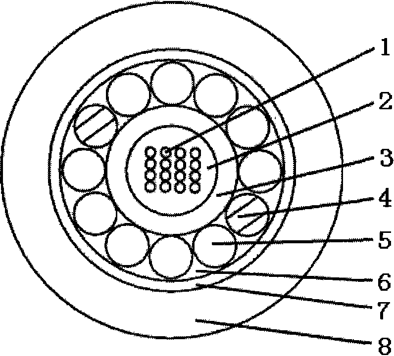
[0021] please see figure 1 , a central bundle tube type optical cable, which includes a circular central bundle tube 3, which contains an optical fiber 1 and an internal resistance water object 2, along the outer wall of the central bundle tube, centered on the axis of the central beam tube, extending longitudinally and in a single The reinforcing member 4 is covered with a helical direction or a clockwise / counterclockwise staggered direction, and the reinforcing member 4 is provided with a protective layer 7, and there is an external water blocking object 6 in the gap between the protective layer 7 and the central bundle tube to protect A sheath layer 8 is provided outside the layer 7; the characteristic is that the reinforcing member 4 contains at least ten filling pieces 5, and the filling pieces are symmetrically distributed outside the central bundle tube, and the pitch of the spiral is 300mm.

Embodiment 2

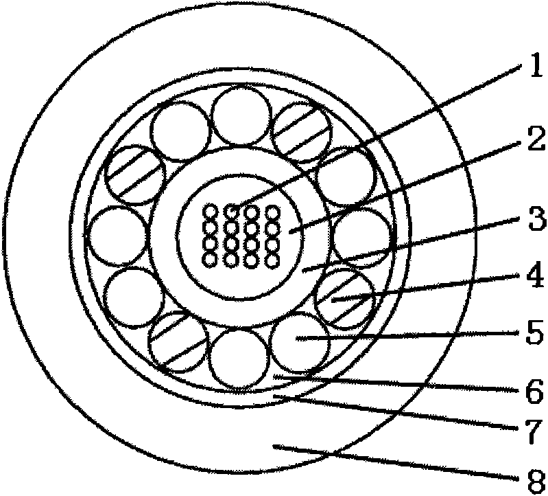
[0023] please see figure 2 , basically the same as the implementation example 1, the difference is that: the two filling pieces are replaced by reinforcing pieces; the filling pieces are also symmetrically distributed outside the central bundle tube.

Embodiment 3

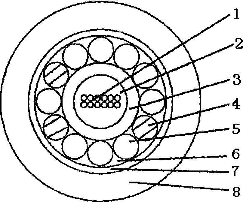
[0025] please see image 3 , basically the same as the implementation example 1, the difference is that: the number of optical fibers is changed from 16 to 12; one of the fillers is replaced by a reinforcement; the fillers are also asymmetrically distributed outside the central beam tube .

[0026] In the present invention, since the reinforcing member is in direct contact with the central bundle tube and tightly wrapped on the central bundle tube in a spiral manner, it effectively prevents the shrinkage of the central bundle tube when the temperature cycle changes, so that the optical fibers in the splice box will not be affected by temperature. Changes are easy to break; in addition, due to the inclusion of non-metallic fillers in the reinforcement, the weight of the optical cable is greatly reduced, and the requirements for the tower and its foundation are reduced. Therefore, the cost is greatly saved.


PUM

PropertyMeasurementUnit
Pitchaaaaaaaaaa
Pitchaaaaaaaaaa

Abstract

The invention relates to the technical field of cables, in particular to a center beam tube type cable, which comprises a center beam tube (3) containing optical fibers (1) and internal water resisting objects (2). A reinforcer (4) is coated along the outer wall of the center beam tube in a longitudinal extending and spiral mode by taking the axis of the center beam tube as a center, and the reinforcer (4) is externally provided with a protective layer (7), an external water resisting object (6) is arranged between the protective layer (7) and the center beam tube, and a sheath layer (8) is arranged outside the protective layer (7). The center beam tube type cable is characterized in that in at least one filler (5) is contained in the reinforcer (4). In the invention, because the reinforcer directly contacts with the center beam tube and is tightly wrapped on the center beam tube, the contraction of the center beam tube due to temperature change is effectively resisted, and the opticalfibers are effectively protected; in addition, because the non-metallic filler is contained in the reinforcer, the weight of the cable is greatly decreased, the requirements of towers and foundationsthereof are reduced, and therefore, the cost is greatly reduced.

Description

technical field [0001] The invention relates to the technical field of optical cables, in particular to a central bundle tube type optical cable with an improved structure. Background technique [0002] The communication industry standard of the People's Republic of China "YD / T769-2003 Core Network Optical Cable Center Bundle Tube Communication Outdoor Optical Cable" stipulates the structure of the optical cable, and the listed models include GYXTY, GYXTA, GYXTS, GYXTW, etc., among which GYXTY , GYXTA and GYXTS optical cables are in the form of a central beam tube, the optical fiber is placed in the tube, and a full circle of steel wire is wrapped around the tube; although this structure effectively protects the optical cable, it consumes a lot of steel. Therefore, the weight of the entire optical cable is relatively heavy. When multiple optical cables are placed on the tower, the tower will bear a lot of force, so the material and foundation of the tower also need to be ver...

Claims


Application Information

Patent Timeline
IPC IPC(8): G02B6/44
Inventor 沈群华
Owner 沈群华
Why Eureka
Try Eureka