Tape sticking device

A gluing device and gluing technology, applied in the direction of sustainable manufacturing/processing, electrochemical generators, electrical components, etc., can solve the problems of occupying effective battery space, tension force cell pressure, waste tape, etc., to reduce Occupancy, stress reduction, adverse effects reduction effects

Active Publication Date: 2010-02-17
SHENZHEN YINGHE TECH
View PDF0 Cites 21 Cited by
  • Summary
  • Abstract
  • Description
  • Claims
  • Application Information

AI Technical Summary

Problems solved by technology

The current method of pasting the termination tape is mostly the winding and pasting method, which is a waste of tape and takes up the effective space of the battery; and when winding and pasting, one end of the tape is first attached to the end of the pole piece, and the other end is stretched and wound. The roll is attached to the cell, and tension is generated in the pole piece and puts pressure on the cell
This will have a great adverse effect on the performance of the square lithium battery; the amount of adhesive tape used is also large, which is not conducive to reducing costs

Method used


Image

  • Tape sticking device
  • Tape sticking device

Examples


Embodiment 1

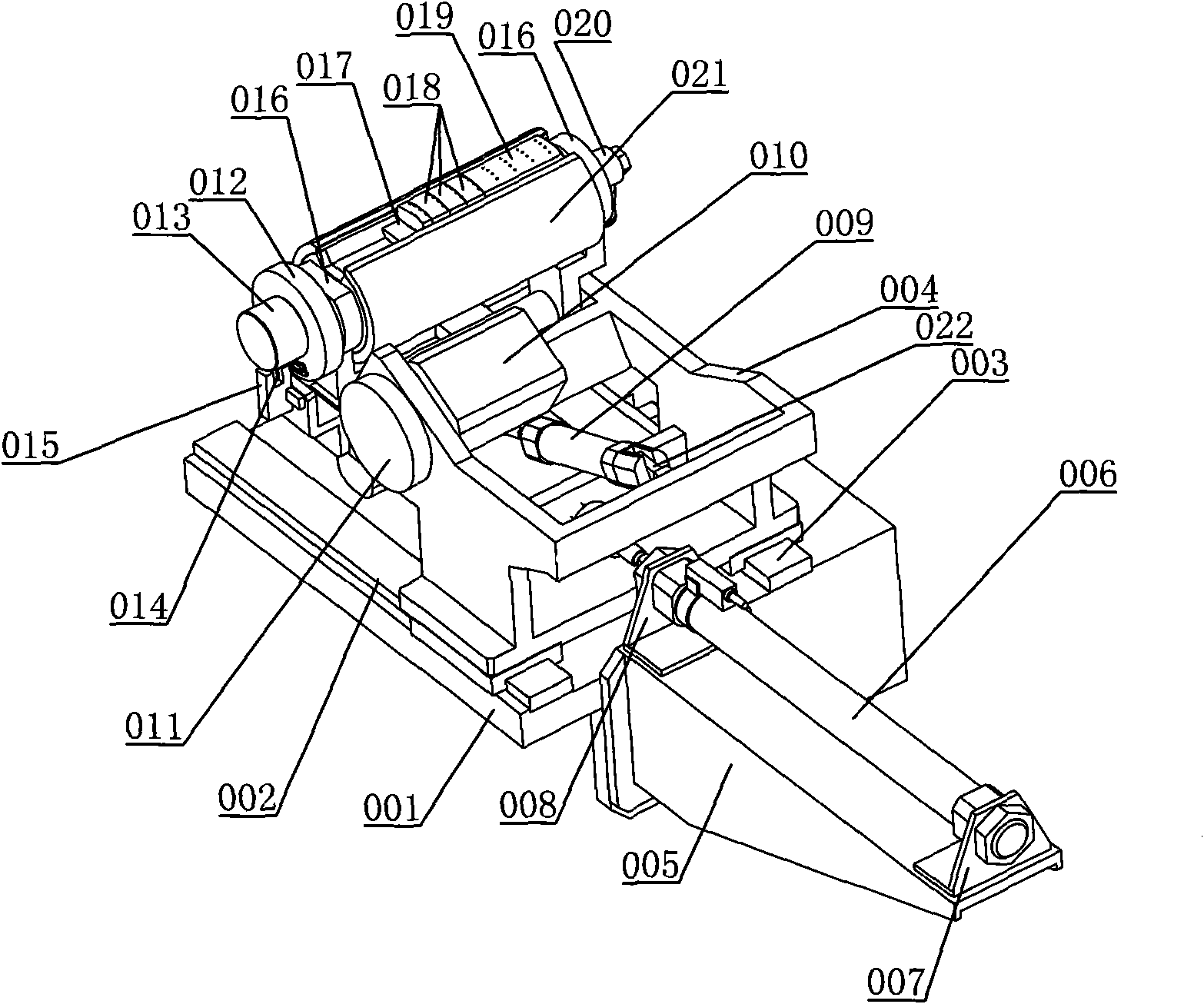
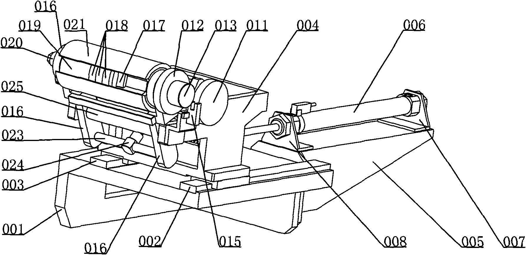
[0017] figure 1 and figure 2 A specific embodiment of the invention is shown.

[0018] like figure 1 and figure 2 As shown, the gluing device includes a control unit (not shown in the accompanying drawings), a mounting plate 001, a first guide rail 002, a second guide rail 003, a support frame 004, a cylinder mounting plate 005, a first cylinder 006 (that is, a drive support frame movement power mechanism), the first cylinder bracket 007, the second cylinder bracket 008, the second cylinder 009, the servo motor 010, the first friction wheel 011, the second friction wheel 012, the gland 013, the induction plate 014, the sensor 015 , swing arm 016, stopper 017, movable rubber suction block 018, fixed rubber suction block 019, vacuum suction joint 020, rubber sticking roller 021, cylinder installation block 022, pull rod 023, cylinder connection block 024 and connecting shaft 025. The servo motor 010, the first friction wheel 011 and the second friction wheel 012 constitute...

Embodiment 2

[0022] Embodiment 1 can also be simplified to obtain Embodiment 2: the swing frame and the second cylinder 009 are removed, and the gluing roller 021 is directly pivotally connected to the supporting frame 004 .

[0023] When working, the piston rod of the first cylinder 006 retracts, the support frame 004 returns to the glue suction position, and the movable glue suction block 018 and the fixed glue suction block 019 are located directly below the adhesive tape (the positions of the sensor 015 and the induction piece 014 correspond to each other) ; If the adhesive roller 021 is not at the angle corresponding to the positions of the sensor 015 and the induction sheet 014, the servo motor 010 works until the induction occurs between the sensor 015 and the induction sheet 014, and the control unit controls the servo motor 010 to stop according to the signal of the sensor 015, At this time, the movable glue-absorbing block 018 and the fixed glue-absorbing block 019 are directly be...


PUM


Abstract

The invention provides a tape sticking device, which comprises a support frame, a power mechanism for driving the support frame to move, and a tape sticking and driving mechanism. The support frame isprovided with a tape sticking roller capable of rotating around the self central axial line; the sticking roller is provided with a tape absorbing block communicated with a vacuum system; and the tape sticking and driving mechanism and the tape sticking roller form a driving matched relationship which makes the tape sticking roller rotate around the self central axial line. By adopting the tape sticking device, tapes can be stuck on pole pieces and rolling cores in a non-tightening state, thereby reducing the pressure on battery cells caused by the tension of the tapes and further reducing disadvantage influences on the battery performances. Meanwhile, the consumtion of the tapes is less, thereby reducing the occupation of the tapes to the inner space of the battery, being beneficial forreducing the cost and improving the utilization efficiency and the capacity of the battery; and the tape sticking device has simple structure and easy implementation.

Description

【Technical field】 [0001] The invention relates to battery manufacturing technology, in particular to a gluing device for pasting adhesive tapes in a non-tensioned manner. 【Background technique】 [0002] The battery cell of a lithium battery is formed by winding a diaphragm and a pole piece. During the winding, the end of the pole piece must be stuck with tape. This process is called termination tape. The current method of pasting the termination tape is mostly the winding and pasting method, which is a waste of tape and takes up the effective space of the battery; and when winding and pasting, one end of the tape is first attached to the end of the pole piece, and the other end is stretched and wound. The roll is attached to the cell, and tension is generated in the pole piece and puts pressure on the cell. This will have a great adverse effect on the performance of the square lithium battery; the amount of adhesive tape used is also large, which is not conducive to reducin...

Claims


Application Information

Patent Timeline
Patent Type & Authority Applications(China)
IPC IPC(8): H01M10/38H01M6/14
CPCY02E60/12Y02E60/10Y02P70/50
Inventor 王维东王胜玲
Owner SHENZHEN YINGHE TECH
Why Eureka
Try Eureka