Power divider with new structure

A new type of structure and power divider technology, applied in the direction of waveguide devices, electrical components, connecting devices, etc., can solve problems such as parasitic effects, phase inconsistency between signals, etc., achieve improved isolation performance, save volume, and improve the accuracy of simulation design The effect of speed and productivity

Inactive Publication Date: 2010-02-24
UNIV OF ELECTRONICS SCI & TECH OF CHINA
View PDF1 Cites 23 Cited by
  • Summary
  • Abstract
  • Description
  • Claims
  • Application Information

AI Technical Summary

Problems solved by technology

[0006]Aiming at the deficiencies in the prior art power divider transmission line, the purpose of the present invention is to provide a power divider with a new structure to overcome Wilkinson power divider The paras...

Method used


Image

  • Power divider with new structure
  • Power divider with new structure
  • Power divider with new structure

Examples


Embodiment 1

[0042] Its structure is as attached Figure 7-1 As shown, it is an equal power divider, and two branch lines are designed between the two output main branches. Figure 7-1 It is a model diagram, and the dotted line in the figure indicates the transmission path of the signal in the power splitter. Figure 7-2 is the S of the power divider model 11 , S 22 , S 21 , S 32 Graph. It can be seen from the graph that the center frequency of the power divider is 35GHz, and its S 32 The bandwidth corresponding to 11 22 <-19dB.

Embodiment 2

[0044] Its structure is as attached Figure 8-1 As shown, it is an equal power divider, and four branch lines are designed between the two output main branches. Figure 8-1 It is a model diagram, and the dotted line in the figure indicates the transmission path of the signal in the power splitter. Figure 8-2 is the S of the power divider model 11 , S 22 , S 21 , S 32 Graph. It can be seen from the graph that the center frequency of the power divider is 34.7GHz, and its S 32 11 22 <-21.6dB.

Embodiment 3

[0046] Its structure is as attached Figure 9-1 As shown, it is an equal power divider, and there are 6 branch lines designed between the two output main branches. Figure 9-1 It is a model diagram, and the dotted line in the figure indicates the transmission path of the signal in the power splitter. Figure 9-2 is the S of the power divider model 11 , S 22 , S 21 , S 32 Graph. It can be seen from the graph that the center frequency of the power splitter is 41GHz, and its S 32 The bandwidth corresponding to 11 22 <-17dB.


PUM


Abstract

The present invention discloses a power divider, wherein a transmission line includes a sub-2 connector, two branch ports of the connector are connected to two output main branches separately, more than two branch lines for communicating the two output main branches are arranged between two output main branches, the branches are designed so that a difference of a sum of a path from a node A to a node B11 and a path from the node A to a node B12, and a path from the node B11 to the node B12 is (Lambadaj/2)*(2p +1) + (Lambadaj/2)*Zeta, and the branches of other nodes are designed so that a difference of a sum of a path from a node Bk1 to a node B(k-1)1 and a path from the node B(k-1)1 to a node B(k-1)2 as well as a path from the node B(k-1)2 to a node Bk2, and a path from the node Bk1 to the node Bk2 is (Lambadai/2)*(2m+1) + (Lambadai/2) * Delta. The output and input of the invention are matched well, there is a good separation between two output ends, and overcomes autoeciousness effects of Wilkinson power divider caused by insulation electric resistances and a problem that a phase of a signal outputted from a directly-connecting end is inconsistent to that of a signal outputted from a coupling end of a branch line electric bridge power divider.

Description

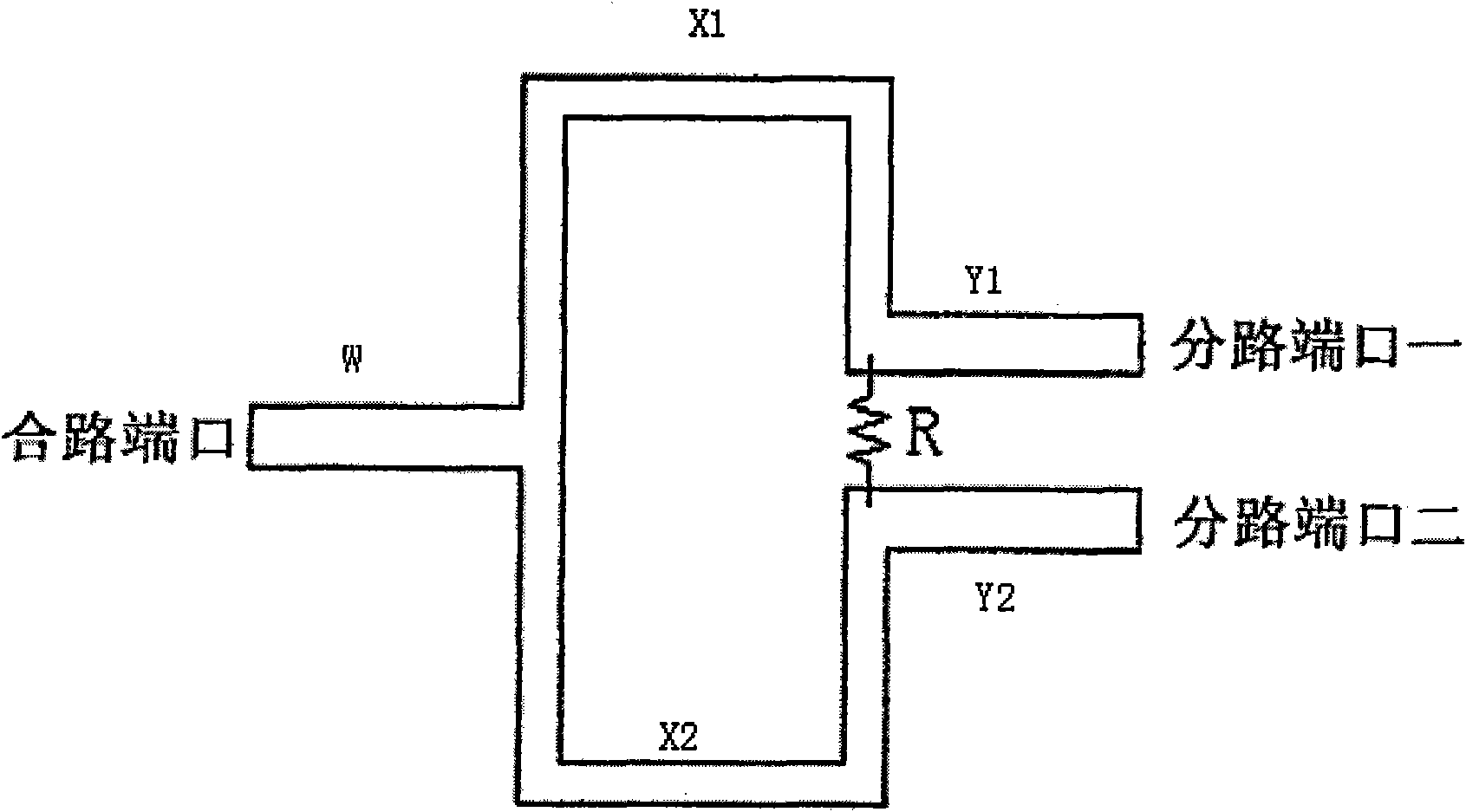
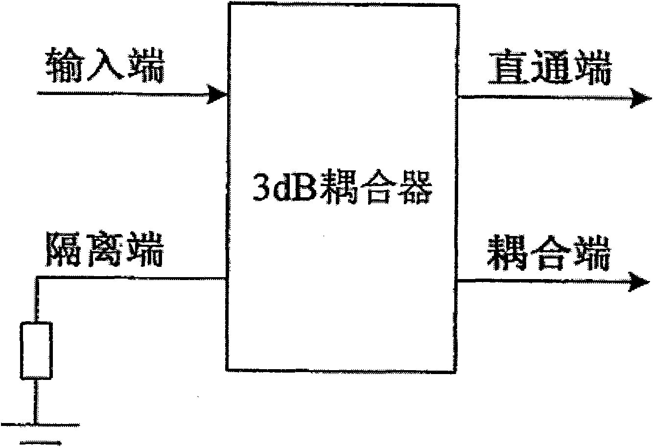
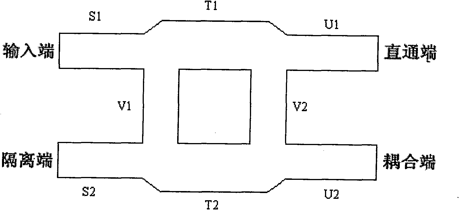
technical field [0001] The present invention relates to a microwave transmission device, more specifically, to a microwave transmission power divider. Background technique [0002] A power divider (referred to as a power divider) is a multi-port microwave device that divides the input power into several equal or unequal power outputs. In high-frequency systems such as microwave and millimeter waves, it is necessary to distribute the transmitting or receiving power to each unit in a certain proportion. Therefore, microwave and millimeter wave power dividers have been widely used in microwave and millimeter wave components and systems, and are also a key components. There are many realization forms of power divider, such as various 3dB bridge couplers, branch line bridge couplers, ring bridge couplers, Wilkinson power dividers and other power dividers with various structures. The functional component of the power divider is the transmission line that constrains or guides the...

Claims


Application Information

Patent Timeline
IPC IPC(8): H01P5/12H01P5/16
Inventor 张勇吴鹏张琴王志刚徐锐敏延波
Owner UNIV OF ELECTRONICS SCI & TECH OF CHINA
Why Eureka
Try Eureka