
Linearly polarized antenna

A technology of linearly polarized antennas and loops, which can be used in the directions of antennas, loop antennas, and antenna arrays that are energized separately, and can solve problems such as inconvenient applications

Inactive Publication Date: 2010-02-24
PRIME ELECTRONICS & STATELLITCS
View PDF0 Cites 3 Cited by
  • Summary
  • Abstract
  • Description
  • Claims
  • Application Information

AI Technical Summary

Problems solved by technology

If the known import antenna is to meet this requirement, its size will increase according to the number of rings, which has the problem of inconvenient application due to the limited space.

Method used


Image

  • Linearly polarized antenna
  • Linearly polarized antenna
  • Linearly polarized antenna

Examples


Embodiment Construction

[0034] In order to illustrate the structure, features and functions of the present invention in detail, the following preferred embodiments are given together with the accompanying drawings for detailed description.

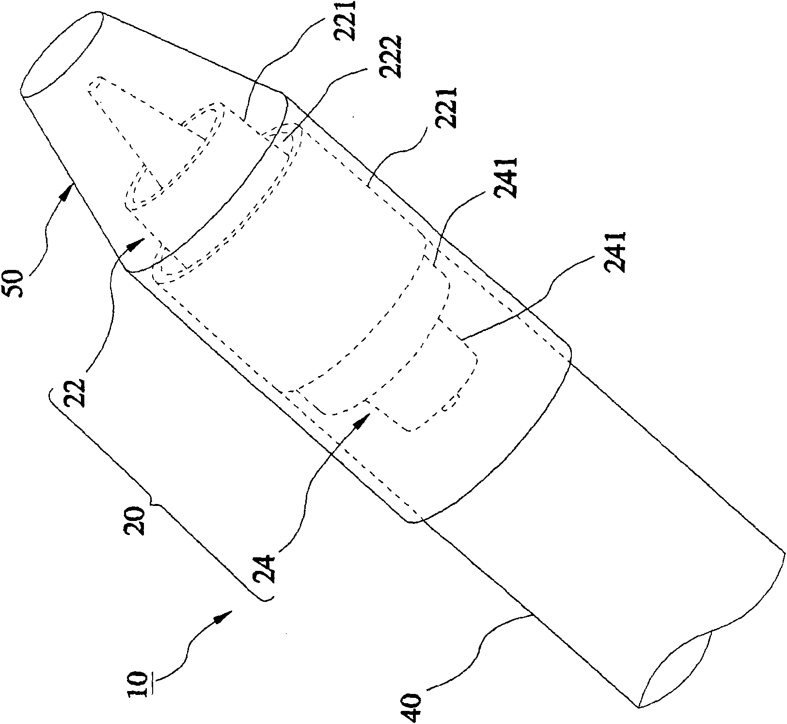
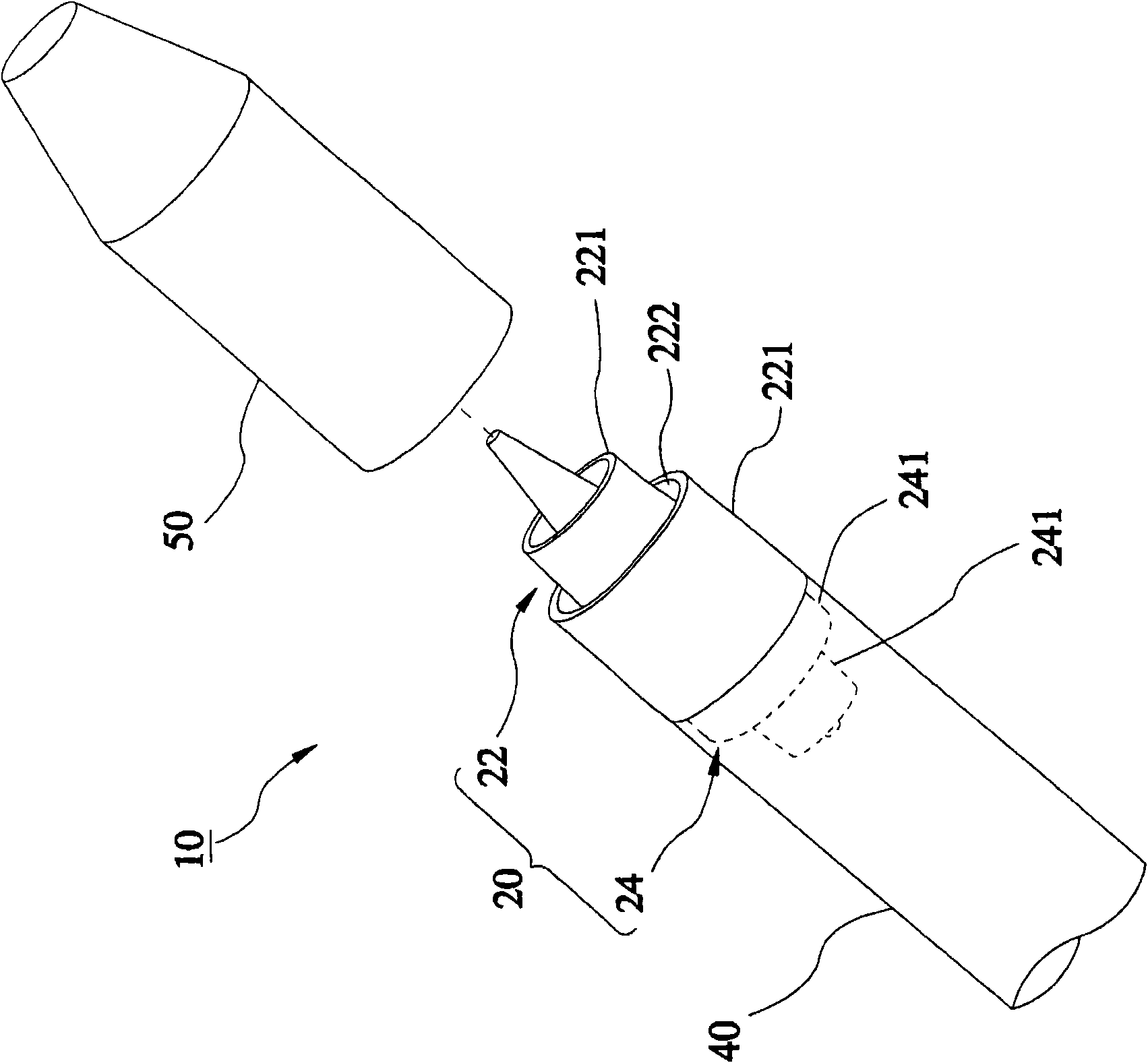
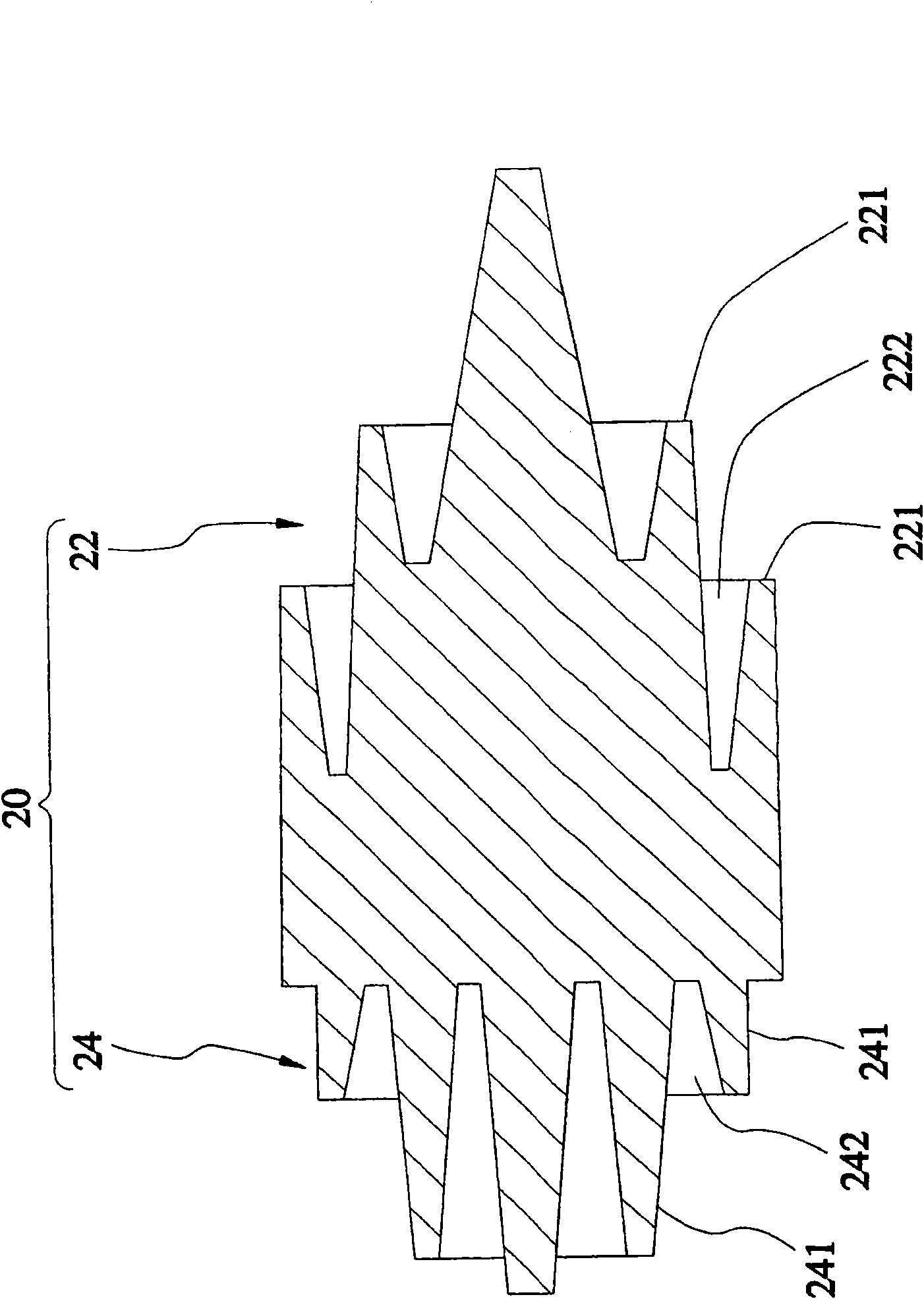
[0035] see Figure 1 to Figure 3 , the linearly polarized antenna 10 provided by the first preferred embodiment of the present invention includes: a body 20 , a waveguide 40 and a cover 50 .

[0036] The body 20 can define a head 22 and a body 24; the head 22 has two first annular portions 221 with different diameters, and the number of these first annular portions 221 is only for illustration and not as a limitation essentials. The first annular portions 221 are arranged coaxially with the axial center of the body 20 as the axis, and a first annular groove 222 is formed between the first annular portions 221 . The first annular portions 221 mainly determine antenna gain, directivity, and side wave suppression. The body 24 has two second annular portions 241 w...


PUM


Abstract

A linearly polarized antenna comprises a body which can define a head part and a body part. The head part is provided with a plurality of first ring-shaped parts in different diameters, the first ring-shaped parts are distributed in a coaxial manner by taking the axial direction of the body as the axis, and first ring-shaped grooves are formed among the first ring-shaped parts. The body section isprovided with a plurality of second ring-shaped parts in different diameters, the second ring-shaped parts are distributed in a coaxial manner by taking the axial direction of the body as the axis, and second ring-shaped grooves are formed among the second ring-shaped parts. The extension directions of the first ring-shaped parts are opposite to the extension directions of the second ring-shapedparts.

Description

technical field [0001] The present invention is related to satellite receiving equipment, in particular to a linearly polarized antenna, which is mainly used in a low noise block down-converter (LNB) to replace the known sink antenna. Background technique [0002] In recent years, due to the rapid development of wireless communication and multimedia, consumers' demand for multimedia has been continuously increasing. In terms of satellite TV, a single satellite program can no longer meet the needs of the public. The integration of multiple satellite programs is the current trend. The early multi-satellite receiving system used a single receiving dish (dish) for a single low noise block down-converter (hereinafter referred to as LNB); The satellite receiving system has been developed into a single receiving dish paired with multiple LNBs to achieve the purpose of receiving signals from multiple satellites. [0003] However, since the azimuth angles of multiple satellites are ...

Claims


Application Information

Patent Timeline
Patent Type & Authority Applications(China)
IPC IPC(8): H01Q7/00H01Q13/00H01Q21/06
Inventor 柯庆来
Owner PRIME ELECTRONICS & STATELLITCS
Learn More