Method for obtaining dynamic shape of foot model

A dynamic shape and acquisition method technology, applied in the measurement device of feet or shoe lasts, image data processing, clothing, etc., can solve the problems of limited use range, sparseness, and high cost of optical marking points, so as to make up for blind spots and avoid processing work, cost reduction effect

Inactive Publication Date: 2010-03-03
ZHEJIANG UNIV
View PDF1 Cites 14 Cited by
  • Summary
  • Abstract
  • Description
  • Claims
  • Application Information

AI Technical Summary

Problems solved by technology

The measurement technology based on laser scanning generally has a long scanning period, and the fastest time to scan a foot is more than 4s, which limits it to only measure static objects and cannot measure moving targets. The technology based on laser modulation grating has high requirements on the ambient light of the measurement environment, and generally does not allow changes in the ambient light during the measurement process, which limits the scope of use of this type of technology. In general environments, the measurement of moving targets is difficult. The moving target itself will also change the ambient light, so it is generally used in a dark room
The measurement technology based on stereo vision is mainly used for motion capture. It generally uses optical marking points, which are not sensitive to ambient light, but they are generally sparse and cannot describe the shape of moving targets, and the cost of optical marking points is high. Not conducive to large-scale promotion of the industry
In addition, it is very cumbersome to arrange optical markers on the surface of the target to be captured and to clean up after capture.

Method used


Image

  • Method for obtaining dynamic shape of foot model
  • Method for obtaining dynamic shape of foot model
  • Method for obtaining dynamic shape of foot model

Examples


Embodiment

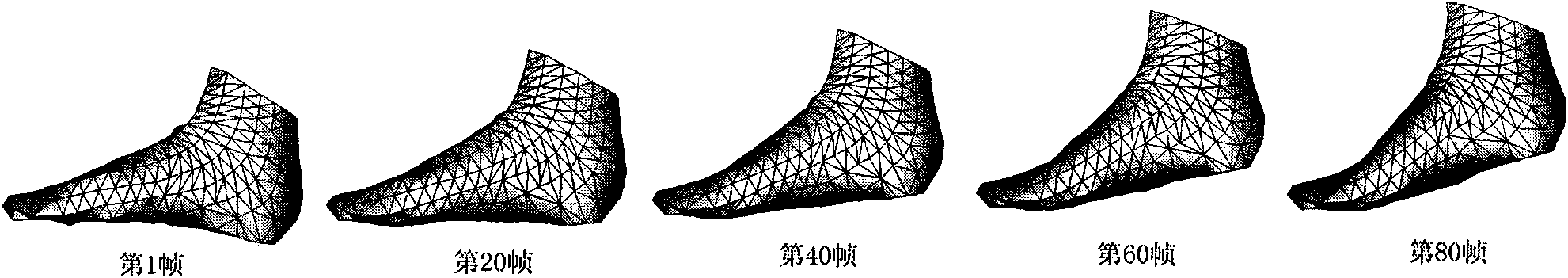
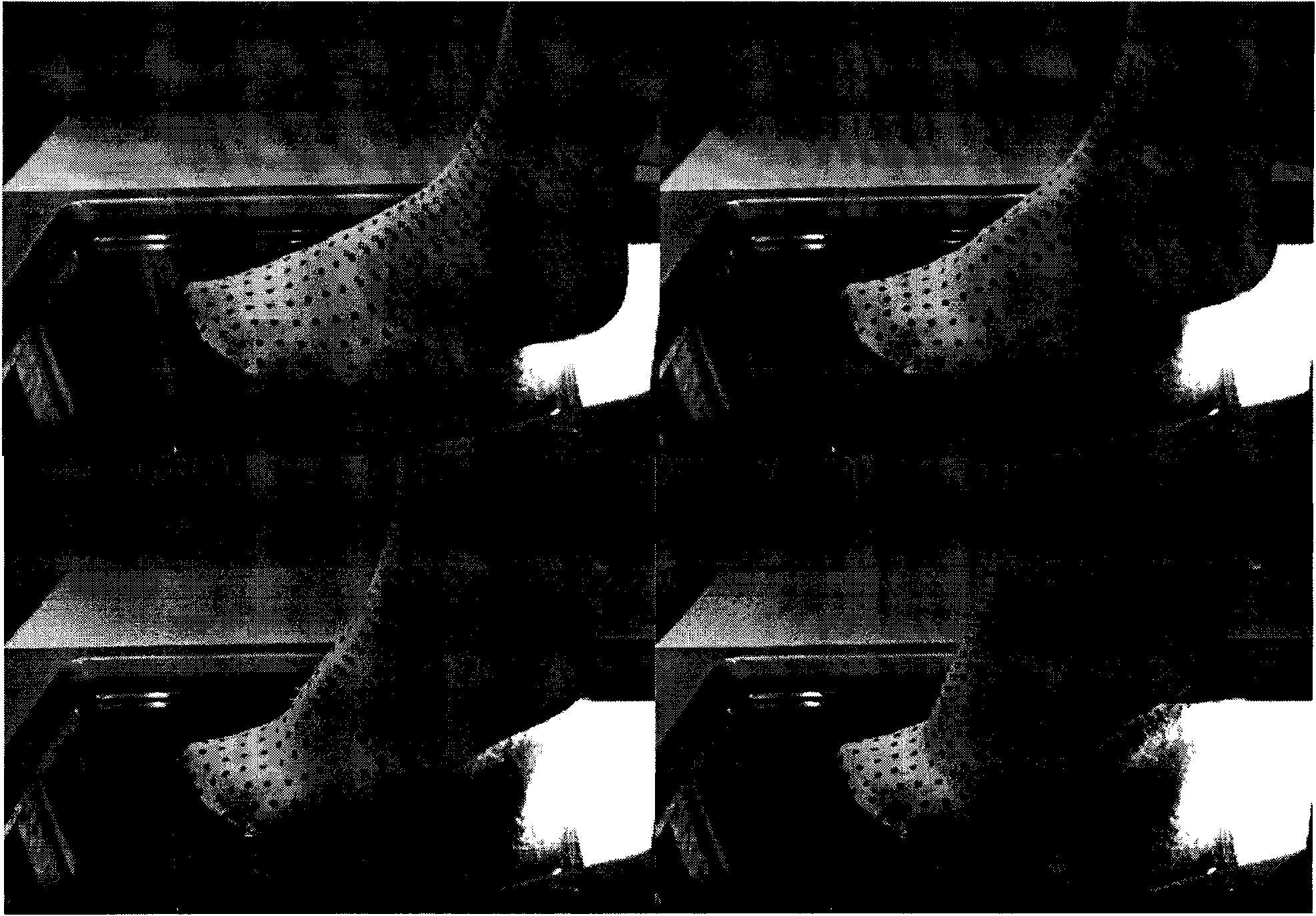
[0062] We first put on socks with marked points on the measured foot shape, and then use 10 cameras distributed around the shooting area to record the first frame of foot shape images from various angles of view; then use several of the 10 cameras (this In the process of realizing the invention, 6) cameras were used to synchronously record the movement and deformation process of the foot shape, and a corresponding number of tracking videos were obtained. The synchronization frame rate of the cameras was 13 frames per second, and the resolution rate of each frame image was 800×600 pixels. Afterwards, the pixel-level precision positions of the two-dimensional image marker points in each frame of the two-dimensional image in the tracking video are extracted. Any disclosed feature extraction method can be used, and the method used in the implementation process of this patent is the Harris feature extraction method. Reconstruct the first frame of 3D foot model as a reference model...


PUM


Abstract

The invention discloses a method for obtaining a dynamic shape of a foot model, which realizes to obtain the three-dimensional shape of foot models at any time during the moving and changing process of human foot, which includes the steps of: wearing socks with marking points on the foot models; using a plurality of cameras to track the positions of the marking points on the socks at any time at aplurality of visual angles in full orientation; implementing binocular camera matching on the visible two-dimensional image marking points tracked in subsequent frames based on the three-dimensionalfoot model of the first frame and then reconstructing a three-dimensional coordinate, thereby obtaining the time of each frame and the three-dimensional positions of the visible marking points; and finally, starting from the three-dimensional foot model of the first frame and obtaining the three-dimensional foot model of the latter frame by iteratively implementing deformation on the three-dimensional foot model of the front frame under the restriction of the position of the visible marking points during the period of the latter frame. The method for obtaining the dynamic shape of the foot model avoids the work of configuration and elimination of the optical marking points in the traditional three-dimensional vision method, and saves the cost caused by using the optical marking point; andmeanwhile, the method for obtaining the dynamic shape of the foot model has less interaction in the whole process, and is convenient and reliable to be used.

Description

technical field [0001] The invention relates to a method for acquiring a dynamic shape of a foot shape, in particular to a method for acquiring the shape of a foot shape during a dynamically changing movement process based on marker points. Background technique [0002] In the technology in the field of three-dimensional measurement of objects, it can be divided into two types: measurement of still objects and measurement of moving objects according to whether the measurement target is moving or not. Classified according to the measurement principle itself, the existing technologies can be mainly divided into measurement technology based on laser scanning, measurement technology based on laser modulation grating, and stereo vision technology. The measurement technology based on laser scanning generally has a long scanning period. At present, the fastest time to scan a foot is more than 4s, which limits that it can only measure static objects and cannot measure moving targets...

Claims


Application Information

Patent Timeline
Patent Type & Authority Applications(China)
IPC IPC(8): A43D1/02G06T17/00
Inventor 耿卫东高飞潘云鹤
Owner ZHEJIANG UNIV
Why Eureka
Try Eureka