Contact assembly of isolating switch

A technology of contact assembly and isolation switch, which is applied in the directions of air switch parts, contact meshing, etc., can solve the problems of difficult processing of spring components, limitation of contact pressure, limitation of spring elastic coefficient, etc.

Inactive Publication Date: 2010-03-03
闫淼江
View PDF1 Cites 15 Cited by
  • Summary
  • Abstract
  • Description
  • Claims
  • Application Information

AI Technical Summary

Problems solved by technology

This leads to difficulties in the processing of the spring member, and it is impossible to use a thicker material to manufacture the spring, so that the elastic coefficient of the spring is limited, which in turn limits the contact pressure

Method used


Image

  • Contact assembly of isolating switch
  • Contact assembly of isolating switch
  • Contact assembly of isolating switch

Examples


Embodiment approach

[0054] Refer to the attached Figure 8-1 0. Describe in detail the contact assembly according to the second preferred embodiment of the present invention. The difference between the second preferred embodiment and the first preferred embodiment described above lies in the spring member, therefore, only the difference between the two will be described below.

[0055] The spring member of the contact assembly according to this embodiment includes two U-shaped leaf springs 81 and 82, such as Figure 10A with 10B Shown, and, two plate springs 81 and 82 intersect with each other, and the U-shaped bottom of the first U-shaped plate spring 81 is provided with a hole 811, so that the coupling rod 9 passes through the hole 811, and connects with the second U-shaped spring 81. The U-shaped bottom of the leaf spring 82 is connected. Such as Figure 10C As shown, one end connected with the second U-shaped leaf spring 82 of the connecting rod 92, hereinafter referred to as the front en...


PUM


Abstract

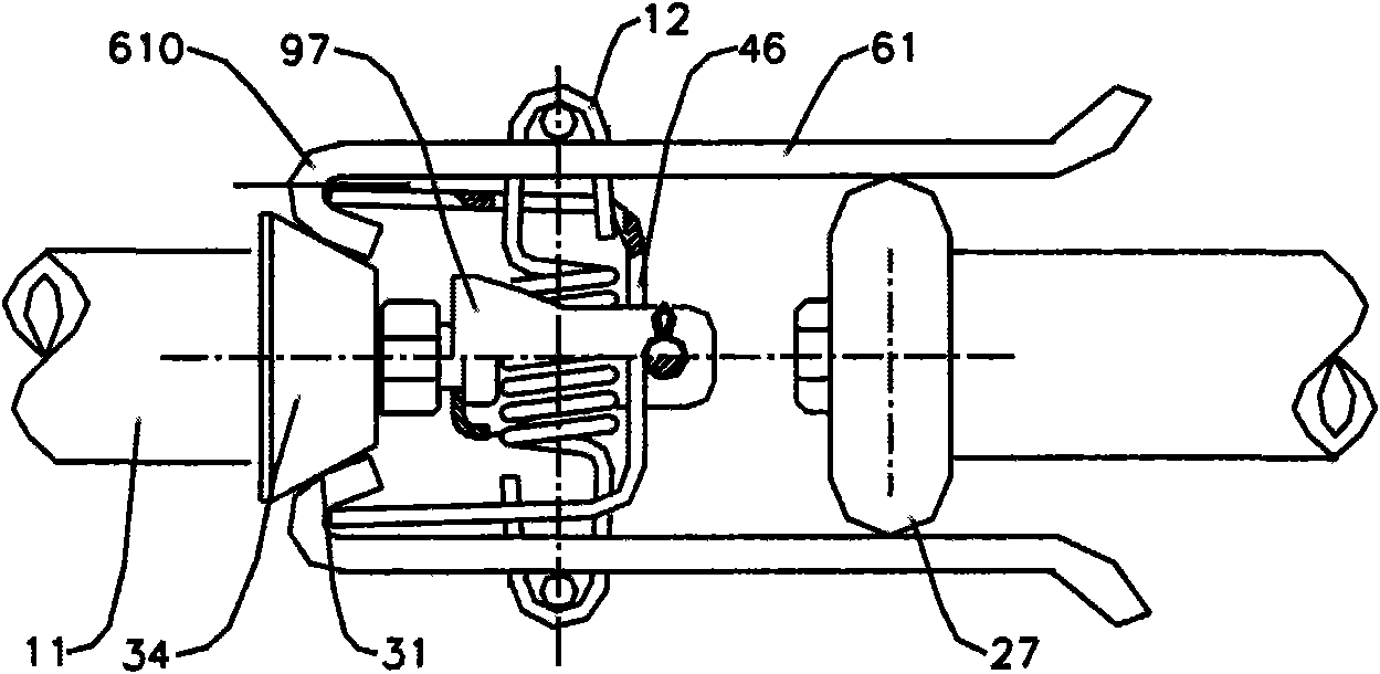
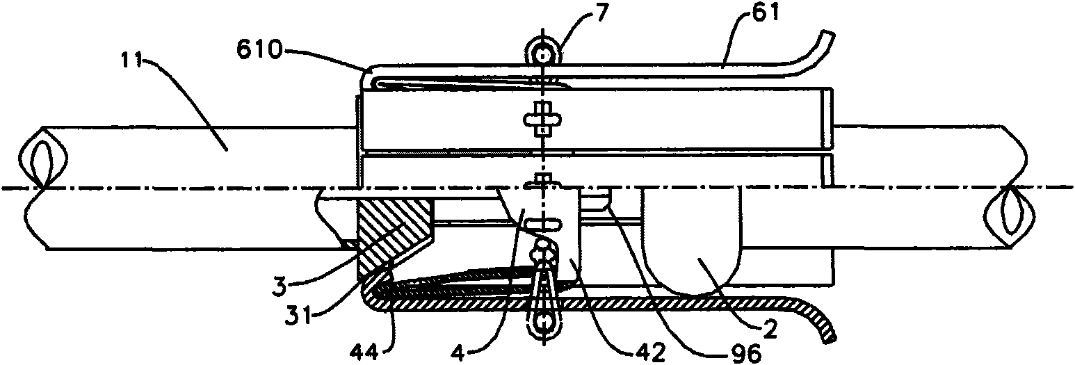
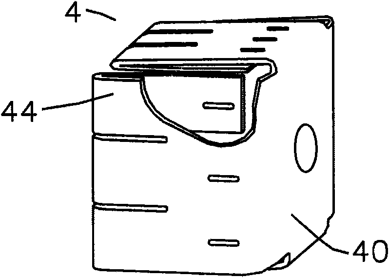
The invention discloses a contact assembly of an isolating switch, comprising a main contact (1) and an involutory contact (2), wherein the main contact (1) comprises an electric conduction base (3),a plurality of sensing fingers (6) and a spring component (4), wherein the electric conduction base (3) is provided with an inclined electric conduction contact surface (31), and the plurality of sensing fingers (6) are respectively connected with the spring component (4) so as to lead the rear ends of the sensing fingers (6) to be contacted with the electric conduction contact surface (31) of theelectric conduction base (3) in a conductive way under the action of the spring component (4). The contact assembly is characterized in that the rear ends of the sensing fingers (6) are straight. Asthe rear ends of the sensing fingers are set to be straight structure, the contact wire length between the rear ends of the sensing fingers and the electric conduction contact surface of the electricconduction base can be prolonged, and the self-cleaning function for a rear contact can be better realized.

Description

technical field [0001] The present invention relates to a high voltage isolating switch, and more particularly to a contact assembly in a high voltage isolating switch. Background technique [0002] High-voltage isolating switches are the most widely used electrical equipment in power systems. Existing high-voltage isolating switches generally use finger-shaped contact assemblies. Contact fingers and contacts that can be inserted into the pair of fingers, a spring is arranged between the pair of fingers to press the pair of fingers toward each other so that the pair of fingers only rests against the inserted on the contacts. [0003] However, this kind of traditional contact assembly usually has the problem of small contact pressure between the contact fingers and the contact, especially the rear contact has no self-cleaning oxide layer action, and it is easy to attach dust and oxidize and generate heat during outdoor operation, which eventually leads to contact assembly b...

Claims


Application Information

Patent Timeline
Patent Type & Authority Applications(China)
IPC IPC(8): H01H31/02H01H1/38H01H1/44
Inventor 闫淼江
Owner 闫淼江
Why Eureka
Try Eureka