Micro low-temperature co-fired ceramic duplexer used for GSM/DCS

A low-temperature co-fired ceramic and duplexer technology, applied in the field of wireless communication, can solve the problems of large insertion loss, increased circuit board area, large component interference, etc., to reduce parasitic capacitance effects, improve duplexer performance, and achieve The effect of miniaturization

Inactive Publication Date: 2010-03-03
SHANGHAI JIAO TONG UNIV
View PDF3 Cites 13 Cited by
  • Summary
  • Abstract
  • Description
  • Claims
  • Application Information

AI Technical Summary

Problems solved by technology

[0004] After searching the literature of the prior art, it is found that the patent document number CN1661912A proposes a lumped duplexer prototype that can suppress the loss of multiple frequency band signals transmitted along the side of the high-pass filter part and the side of the low-pass filter part respectively. It can be seen from the general prototype that four resonators and two capacitors and inductors were introduced in the patent, which resulted in too many components, which also caused excessive interference between components when converted into an actual production and processing model, thus Seriously affect the performance of the duplexer, and such too many components are not conducive to the miniaturization of the duplexer, and from the simulation results given later, it can be seen that although the duplexer can meet the requirements of high isolation, the insertion loss Relatively large, which makes this kind of lumped prototype cannot be widely used in practice, and can only provide a theoretical reference
[0005] In addition, US Patent Document No. US2003 / 0058063A1 and Patent Document No. US2006 / 0006960A1 both involve the use of many ground planes to separate circuit components. Although this effectively blocks mutual coupling and parasitic effects between circuit components, it also Increased board area, impractical for miniaturized devices

Method used


Image

  • Micro low-temperature co-fired ceramic duplexer used for GSM/DCS
  • Micro low-temperature co-fired ceramic duplexer used for GSM/DCS
  • Micro low-temperature co-fired ceramic duplexer used for GSM/DCS

Examples


Embodiment Construction

[0031] The embodiments of the present invention are described in detail below. This embodiment is implemented on the premise of the technical solution of the present invention, and detailed implementation methods and specific operating procedures are provided, but the protection scope of the present invention is not limited to the following implementation example.

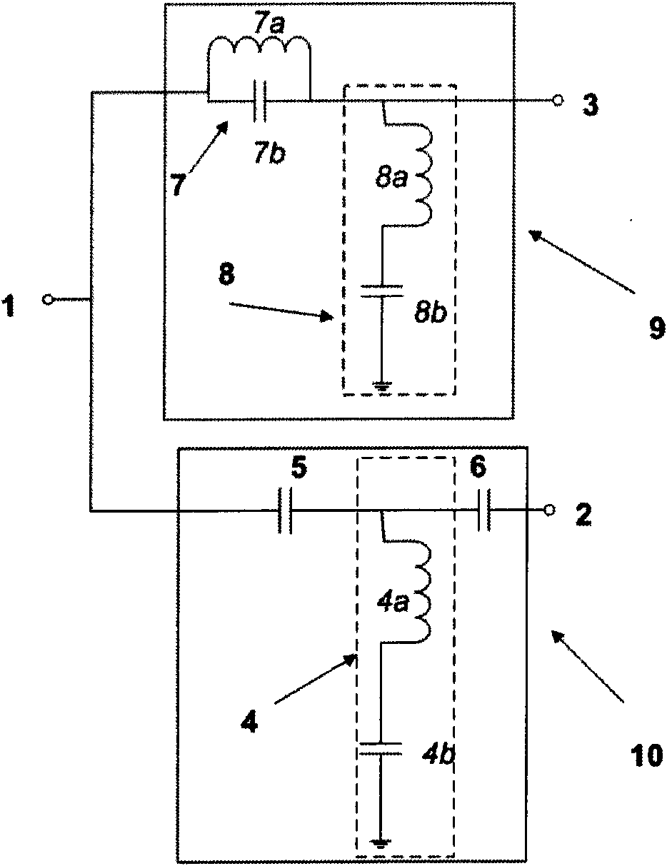
[0032] Such as figure 1 As shown, this example includes: including: a low-pass filtering part 9 and a high-pass filtering part 10, wherein: the input end of the high-pass filtering part 10 is connected in parallel with the input end of the low-pass filtering part 9 as a common antenna port 1, and the output end of the high-pass filtering part 10 serves as The high-frequency output port 2, the output end of the low-pass filtering part 9 is used as the low-frequency output port 3;

[0033] The high-pass filtering part 10 includes: a first series resonator 4, a first capacitive element 5 and a second capacitive eleme...


PUM


Abstract

The invention relates to a micro low-temperature co-fired ceramic duplexer used for a GSM / DCS, belonging to the technical field of wireless communication elements and comprising a high-pass filteringpart and a low-pass filtering part, wherein the input end of the high-pass filtering part and the input end of the low-pass filtering part are connected in parallel as public antenna ports; the outputend of the high-pass filtering part is taken as a high-frequency output port, and the output end of the low-pass filtering part is taken as a low-frequency output port. The invention enables that theduplexer can be flexibly allocated in three-dimensional space by adopting a multilayer micro low-temperature co-fired ceramic technology, thereby leading the structure to be more compact and achieving the miniaturization aim. The allocation of the micro low-temperature co-fired ceramic duplexer can reduce the parasitic capacitance effect to large extent in the circuit operation and ensures that the parasitic capacitance part is added in an allocated capacitor, and the quantity value of the capacitor of the parasitic capacitance part is still equal to the originally-designed quantity value.

Description

technical field [0001] The invention relates to a device in the technical field of wireless communication, in particular to a miniature low-temperature co-fired ceramic duplexer for GSM / DCS. Background technique [0002] With the continuous development and improvement of the mobile communication system, the requirements for mobile communication equipment are getting higher and higher, which continuously promotes the miniaturization and multi-mode of the mobile phone system, that is, it can be compatible with GSM900, DCS1800, PCS, IS -95 and 3G systems, as well as the development of high-performance, thus promoting the development of duplexers in the direction of low cost, miniaturization, and high frequency band. [0003] In a mobile communication system, the reception and transmission of wireless signals need to pass through the antenna. If one antenna is allocated to the receiver and the transmitter, not only the cost and volume will be increased, but also the signals tra...

Claims


Application Information

Patent Timeline
Patent Type & Authority Applications(China)
IPC IPC(8): H03H7/46
Inventor 孙维婷彭宏利毛军发
Owner SHANGHAI JIAO TONG UNIV
Why Eureka
Try Eureka