
In-situ metallurgical preparation method for molding gradient cutter

An in-situ metallurgy and cutting tool technology, applied in the field of forming gradient cutting tools, can solve the problems of reducing the strength and toughness of cemented carbide, production stop loss, loss and waste of cobalt and tungsten carbide materials, etc.

Inactive Publication Date: 2010-03-10
SHANDONG UNIV OF SCI & TECH
View PDF0 Cites 2 Cited by
  • Summary
  • Abstract
  • Description
  • Claims
  • Application Information

AI Technical Summary

Problems solved by technology

The quality of cemented carbide produced by this process is strongly dependent on process parameters such as mixing uniformity of tungsten carbide powder and cobalt powder, parison compaction, sintering method, sintering temperature and sintering time. A large number of microcracks are formed inside the cemented carbide material, and the subsequent brazing will aggravate the growth and expansion of cracks, which will greatly reduce the strength and toughness of the cemented carbide
The above-mentioned defects lead to a large amount of waste of valuable cobalt and tungsten carbide materials, and at the same time cause production stop losses due to frequent tool replacement
[0003] There is not yet a method to completely solve the above-mentioned process defects

Method used


Image

  • In-situ metallurgical preparation method for molding gradient cutter
  • In-situ metallurgical preparation method for molding gradient cutter

Examples


Embodiment Construction

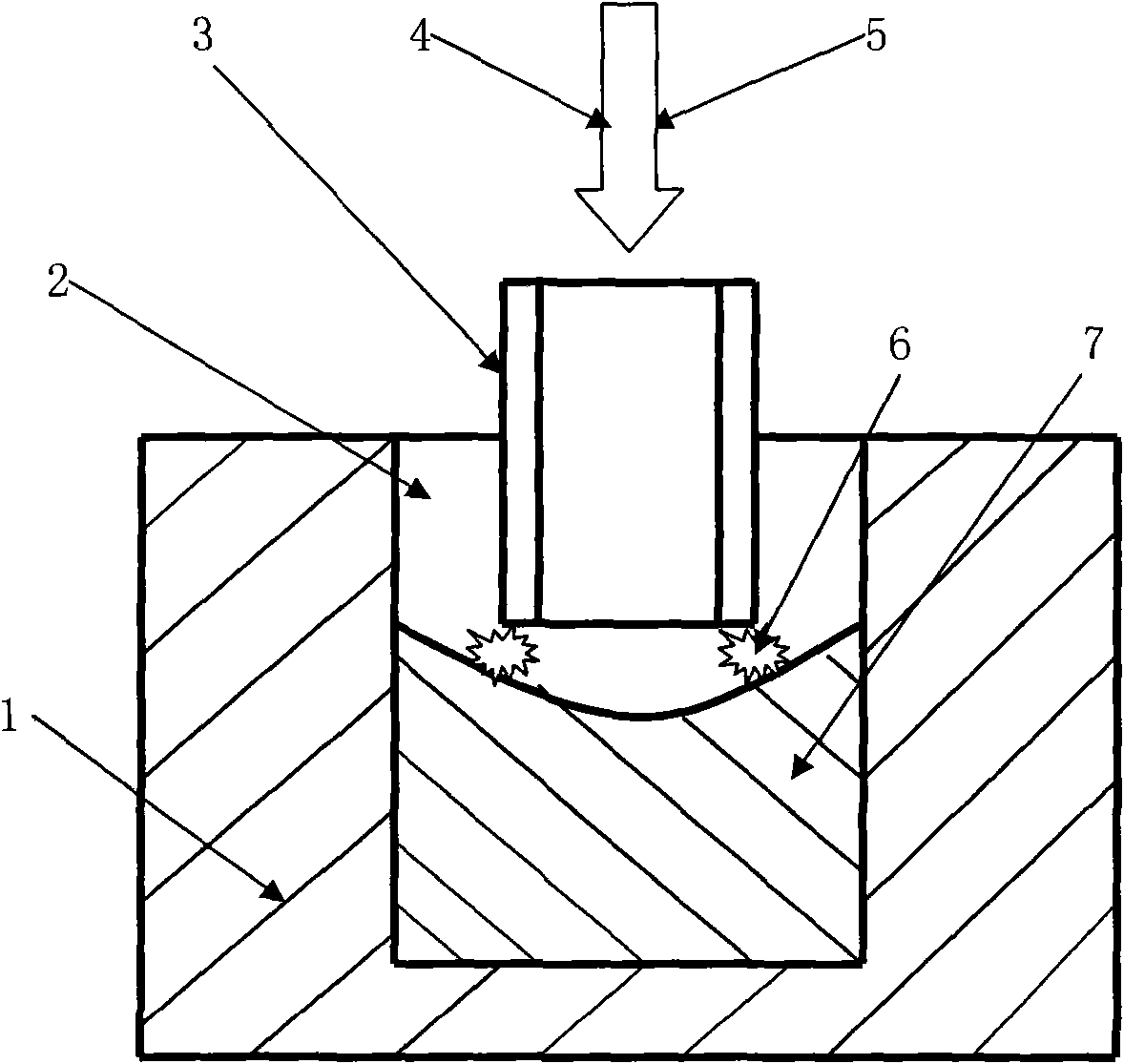
[0009] combine figure 1 figure 2 The embodiments and effects of the present invention will be further described.

[0010] (1), prepare iron-based alloy powder 4 in proportion, and tungsten-based alloy powder 5 of tungsten powder, carbon powder, and iron-based alloy powder, the mixing ratio range of iron-based alloy powder 4 is by weight percentage: iron powder 90~ 95%, nickel powder 1-3%, chromium powder 1-5%, carbon powder 0.2-2%; the mixing ratio range of tungsten powder, carbon powder, and iron-based alloy powder 5 of tungsten-based alloy powder is respectively by weight percentage : Tungsten powder 80-90%, carbon powder 3-8%, iron powder 1-5%, nickel powder 1-5%, chromium powder 1-5%, cobalt powder 1-3%.

[0011] (2), prepare graphite mold 1 according to shape requirements.

[0012] (3), when in-situ metallurgically preparing the forming gradient cutter 7 in the mold cavity 2 of the graphite mold 1, at first the discharge tube 3 made of conductive materials such as gra...


PUM

PropertyMeasurementUnit
hardnessaaaaaaaaaa
hardnessaaaaaaaaaa

Abstract

The invention provides an in-situ metallurgical preparation method for molding gradient cutter, comprising the executive steps of preparing a graphite die according to the shape requirement, conducting a discharging tube made of conductive materials such as graphite or alloy and the like with the anode of a direct current power supply, conducting the graphite die with the cathode of the direct current power supply, slowly descending the discharging tube to the bottom of the die cavity so as to contact an ignition arc, simultaneously sending iron-based alloy powders from the top of the discharging tube in advance, sending in the tungsten-based mixed powder subsequently, and taking out the molding gradient cutter by crushing and removing the graphite die after the graphite die cavity is fulland is solidified and cooled.

Description

technical field [0001] The invention belongs to the technical field of metal cutting or mining cutter preparation, and in particular relates to a preparation method of a forming gradient cutter. Background technique [0002] At present, the cutting tools used in the field of metal cutting and mining are mainly made of cobalt-bonded tungsten carbide cemented carbide. The main production process of cemented carbide is: preparation of cobalt powder → preparation of tungsten carbide powder (first mix tungsten powder and carbon powder Afterwards, it is synthesized in a carbon tube furnace with hydrogen or vacuum at 1400-1600 ° C, and then sieved according to the application) → cobalt powder and tungsten carbide powder are ball milled and mixed (≥ 10 hours) → mixed powder is pressed and formed → high-temperature sintering (depending on the content of cobalt Different between 1380 ~ 1490 ℃ hot isostatic pressing sintering under protective atmosphere) → cemented carbide surface trea...

Claims


Application Information

Patent Timeline
Patent Type & Authority Applications(China)
IPC IPC(8): B22F3/105B22F3/24
Inventor 李惠琪李惠东李扬
Owner SHANDONG UNIV OF SCI & TECH
Learn More