Concrete spreader

A distributing machine and concrete technology, which is applied to the processing of building materials, construction, building construction, etc., can solve the problems of low automation, high labor intensity, and waste of working time, so as to achieve low labor intensity for operators and reduce labor intensity , Easy and fast assembly

Inactive Publication Date: 2010-03-10
夏成新
View PDF0 Cites 20 Cited by
  • Summary
  • Abstract
  • Description
  • Claims
  • Application Information

AI Technical Summary

Problems solved by technology

[0002] With the development of society and the advancement of science and technology, a large number of bridges, power stations, houses and other buildings need to be constructed, and a large number of commercial concrete tank trucks, pump trucks, remote transportation and other appliances have appeared. The existing concrete distribution machine that transports concrete to the point to be poured Most of them have the following defects: 1. The height of the distributing arm cannot be adjusted randomly and lacks flexibility; 2. The distributing arm is short, and the distributing machine moves more times on the same floor, which wastes working time and low work efficiency; 3. 1. The degree of automation is low, and every movement of the machine requires manual operation close to the equipment, which is low in safety; 4. The horizontal rotation of the arm of the cloth machine needs to be manually pulled, and the labor intensity is high; 5. The counterweight part and the host part There is no quick clutch mechanism, and the work efficiency is low; 6. The whole machine is heavy on the top and light on the bottom, the center of gravity is unstable, and it is easy to overturn; it cannot meet the requirements of high efficiency, flexibility, safety, and low labor intensity of modern large-scale industries

Method used


Image

  • Concrete spreader

Examples


Embodiment Construction

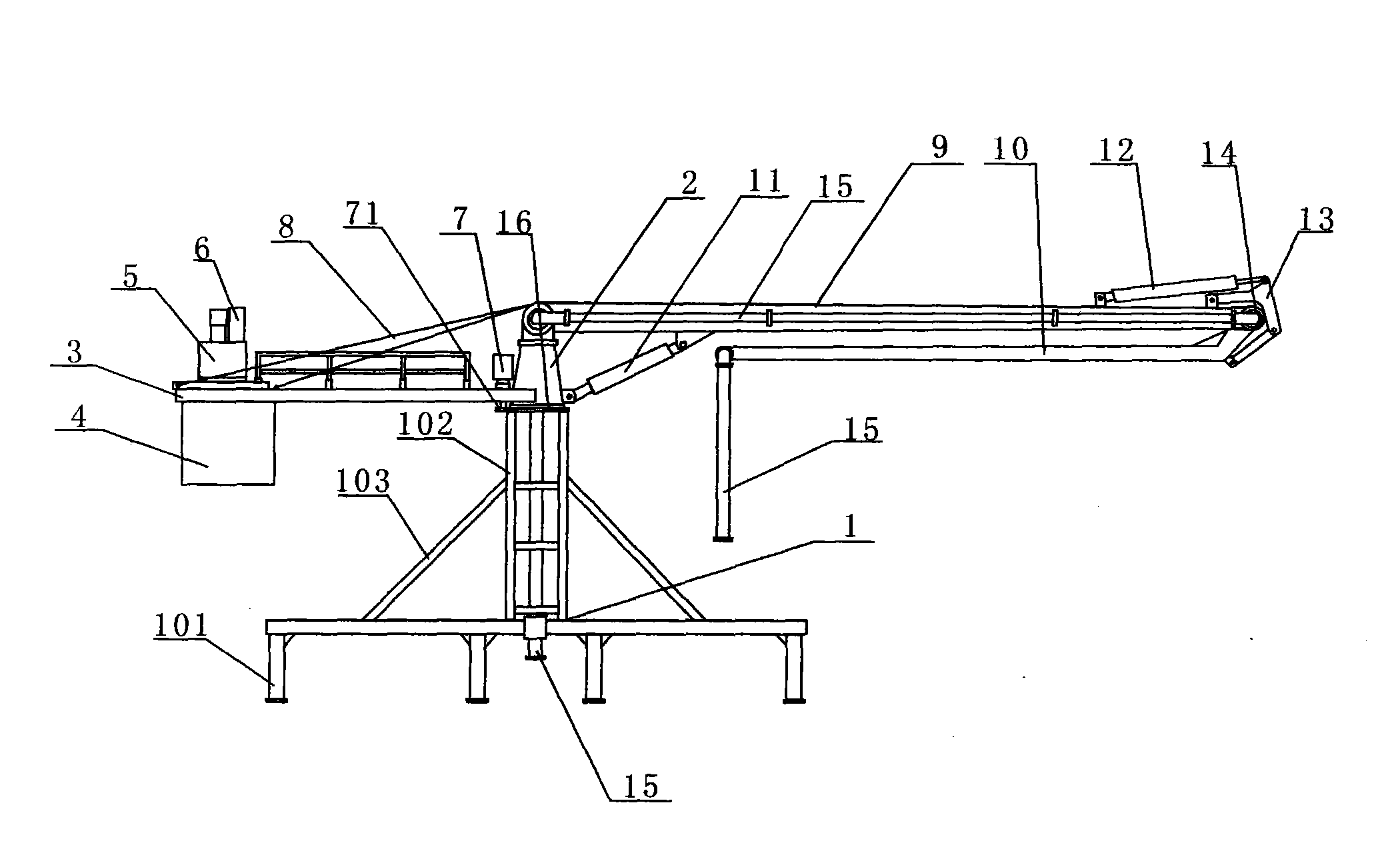
[0012] The present invention will be further introduced below in conjunction with the accompanying drawings and specific embodiments, but not as a limitation of the present invention.

[0013] figure 1 Shown in, the present invention mainly consists of frame (1), conical tower (2), counterweight frame (3), counterweight box (4), hydraulic station (5), electric control box (6), speed reducer ( 7), boom support (8), boom (9), forearm (10), boom oil cylinder (11), forearm oil cylinder (12), connecting rod payment (13), rolling bearing (14) and cloth Composed of tubes (15), it is characterized in that: the conical tower (2) is fixed on the frame (1) through bearing activities, the counterweight frame (3) is fixed on the conical tower (2), and the counterweight box (4) is fixed At the lower end of the counterweight frame (3), the hydraulic station (5) is fixed on the upper end of the counterweight frame (3), the electric control box (6) is fixed on the hydraulic station (5), and t...


PUM


Abstract

The invention discloses a concrete spreader, mainly comprising a rack (1), a conical tower (2), a counterweight frame (3), a counterweight box (4), a hydraulic station (5), an electric cabinet (6), areducer (7), a big-arm support (8), a big arm (9), a small arm (10), a big-arm oil cylinder (11), a small-arm oil cylinder (12), a connecting rod pair (13), an antifriction bearing (14) and a spreading tube (15). The concrete spreader is characterized in that the conical tower (2) is movably fixed on the rack (1) by a bearing, the counterweight frame (3) is fixed on the conical tower (2), the counterweight box (4) is fixed at the lower part of the tail end of the counterweight frame (3), the hydraulic station (5) is fixed on the upper part of the tail end of the counterweight frame (3), the reducer (7) is arranged on the counterweight frame (3), the big-arm support (8) is fixed on the counterweight frame (3), one end of the big arm (9) is movably connected with the conical tower (2) and the other end thereof is connected with the small arm (10) by the antifriction bearing (14), a fixed support of the connecting rod pair (13) is arranged on the big arm (9) and the other fixed support thereof is arranged on the small arm (10), thereby achieving the design purpose.

Description

technical field [0001] The invention relates to a concrete distributing machine for concrete pouring construction at construction sites of bridges, power stations, houses and the like, in particular to a concrete distributing machine which can quickly and accurately deliver concrete to each point to be poured. Background technique [0002] With the development of society and the advancement of science and technology, a large number of bridges, power stations, houses and other buildings need to be constructed, and a large number of commercial concrete tank trucks, pump trucks, remote transportation and other appliances have appeared. The existing concrete distribution machine that transports concrete to the point to be poured Most of them have the following defects: 1. The height of the distributing arm cannot be adjusted randomly and lacks flexibility; 2. The distributing arm is short, and the distributing machine moves more times on the same floor, which wastes working time ...

Claims


Application Information

Patent Timeline
Patent Type & Authority Applications(China)
IPC IPC(8): E04G21/04
Inventor 夏成新
Owner 夏成新
Why Eureka
Try Eureka