Electromagnetic type metering valve

A metering valve, electromagnetic technology, applied in the field of electromagnetically controlled liquid metering valves

Inactive Publication Date: 2010-03-10
HANGZHOU KAMBAYASHI ELECTRONICS
View PDF5 Cites 5 Cited by
  • Summary
  • Abstract
  • Description
  • Claims
  • Application Information

AI Technical Summary

Problems solved by technology

[0006] In order to solve the problem of automatic feeding of liquid detergent, the present invention provides an electromagnetic metering valve, which uses a single electromagnetic coil to measure a set amount of liquid detergent, and flushes out the washing liquid with tap water, and can realize multiple feedings action

Method used


Image

  • Electromagnetic type metering valve
  • Electromagnetic type metering valve
  • Electromagnetic type metering valve

Examples


Embodiment 1

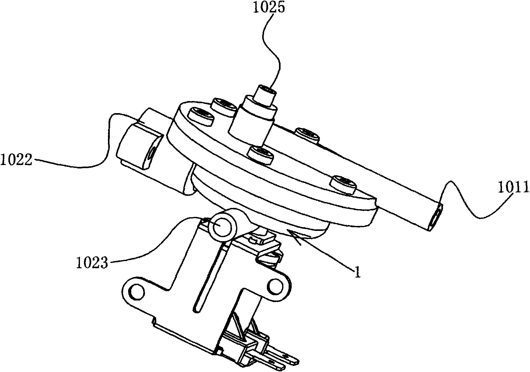
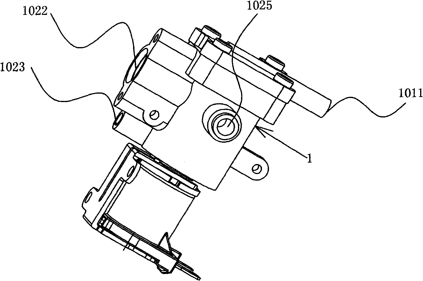
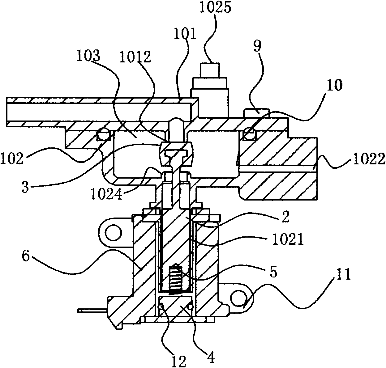
[0046] The electromagnetic metering valve of the present embodiment, such as Figure 1a , Figure 1b , Figure 2a , Figure 2b , Figure 3a , Figure 3b As shown, valve body A101 and valve body B102 formed by resin form valve body 1 with metering chamber 103. Valve body A101 and valve body B102 can be connected and sealed by screws 9 and O-rings 10, or by ultrasonic welding. The method of directly connecting together; adjusting the volume inside the valve body can adjust the capacity of each metering; the valve body B102 has a conduit 1021 connected with the metering chamber 103, the inlet A1011 is formed on the valve body A101, and the valve seat A1012 is formed on the A valve seat B1024, a conduit 1021 and an exhaust port 1025 are formed on the valve body A101 and the valve body B102, and the exhaust port 1025 communicates with the metering chamber 103;

[0047] The inflow port B1022 is directly formed on the valve body B, and the diameter of the inflow port B communicat...

Embodiment 2

[0056] The electromagnetic metering valve of this embodiment is based on the first embodiment, a check valve 7 is set in the inlet B1022 and a ball valve 8 is set at the exhaust port 1025, as Figure 4a , Figure 4b , Figure 5a , Figure 5b , Figure 6a , Figure 6b As shown, the one-way valve has a spool 701 and a one-way valve body 703. One end of the spool runs through the through-hole of the retaining wall in the inlet 1022. A spring 702 is arranged between the retaining wall and the spool 701. The spool is driven by the action of the spring. The other end of the spool is pressed on the sealing surface of the one-way valve body;

[0057] The end portion of the valve core can also be sealed with the valve body by setting an O-ring 704, or can be directly sealed with plastic contact.

[0058] Inflow port B1022 is due to the effect of one-way valve 7 during metering action like this, and the liquid in the metering chamber 103 just can not flow through inflow port B and ...

Embodiment 3

[0061] The electromagnetic metering valve of the present embodiment, such as Figure 7a , Figure 7b , Figure 8a , Figure 8b Show, be on the basis of embodiment one, two, add tee pipe 17 on inlet B, then change fixed iron core 4 into the elongated fixed iron core 18 that has through hole; After electromagnetic coil 6 is energized , the movable iron core 2 is attracted by the magnetic force to move toward the direction of the extended fixed iron core 18, and the piston cap 3 is placed on the valve seat B1024. At this time, the controller opens the external solenoid valve connected to the three-way nozzle A1701, and a part of the tap water The water pressure is applied to the inflow port B1022 through the three-way nozzle C1703, and then enters the metering chamber 103 to mix with the detergent in the metering chamber, and the mixed liquid is squeezed out through the exhaust port 1025 and the outflow port 1023, and flows into the washing machine tank h Inside; the other par...


PUM


Abstract

The invention relates to an electromagnetic type metering valve. The metering valve consists of a valve body, a movable iron core, a piston cap, a fixed iron core, a spring and an electromagnetic loop, wherein the valve body has an inflow port A, an inflow port B, an outflow port and an exhaust port; the inside of the inflow port B is provided with a one-way valve consisting of a valve core, a spring and a one-way valve body; one end of the valve core penetrates a block wall through hole inside the inflow port B, while the spring is sleeved between a block wall and the valve core; the inflow port B is arranged on a valve body B or a valve body A; the inside of the exhaust port is provided with a ball valve; the ball valve has a ball sealer; the valve body B is provided with a positioning structure; the valve body A is provided with a valve seat C; the ball sealer is positioned inside the positioning structure and corresponds to the valve seat C; the inflow port B is connected with a tee pipe; the fixed iron core is a lengthened fixed iron core with a central pore; a bending joint is connected behind the lengthened fixed iron core; and a hose is connected between a tee pipe nozzle and the bending joint. The electromagnetic type metering valve is suitable to be used in detergent release devices such as electric washing machines and dishwashers.

Description

technical field [0001] The present invention relates to electromagnetically controlled liquid metering valves. Background technique [0002] In the past, electric washing machines and electric dishwashing and drying machines using liquid detergents were equipped with a liquid detergent input tank, and the user poured an approximate amount of liquid detergent into the input tank in advance. Enter the liquid detergent delivery tank, and flush the detergent into the washing bucket. This input method will flush all the detergent in the delivery tank into the washing tub, and the user needs to inject detergent in advance every time it is used. In addition, the delivery amount also depends on the user's operation. But washing often requires adjusting the dosage of detergent according to the amount of washing, and it is often difficult for consumers to accurately grasp the amount of washing, so it is difficult to accurately control the dosage of detergent. In order to solve the ...

Claims


Application Information

Patent Timeline
Patent Type & Authority Applications(China)
IPC IPC(8): F16K31/06F16K11/22F16K37/00F16K27/00G01F11/00D06F39/02A47L15/44
Inventor 王华陈国秀
Owner HANGZHOU KAMBAYASHI ELECTRONICS
Why Eureka
Try Eureka