Supercharge Your Innovation With Domain-Expert AI Agents!

Light guide panel

A technology of light guide plate and light source, applied in the field of light guide plate, can solve the problems of poor uniformity of the light guide plate and the like

Inactive Publication Date: 2011-03-16
LITE ON OPTO TECH (CHANGZHOU) CO LTD +2
View PDF0 Cites 0 Cited by
  • Summary
  • Abstract
  • Description
  • Claims
  • Application Information

AI Technical Summary

Problems solved by technology

And this kind of structure emits strong light when the incident light is strong, and weak outgoing light when the incident light is weak, which makes the overall uniformity of the light guide plate not good.

Method used


Image

  • Light guide panel
  • Light guide panel
  • Light guide panel

Examples


Embodiment Construction

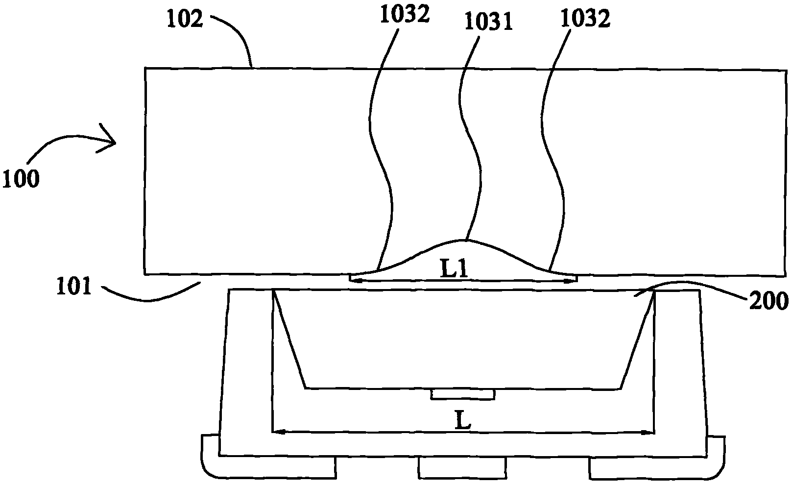
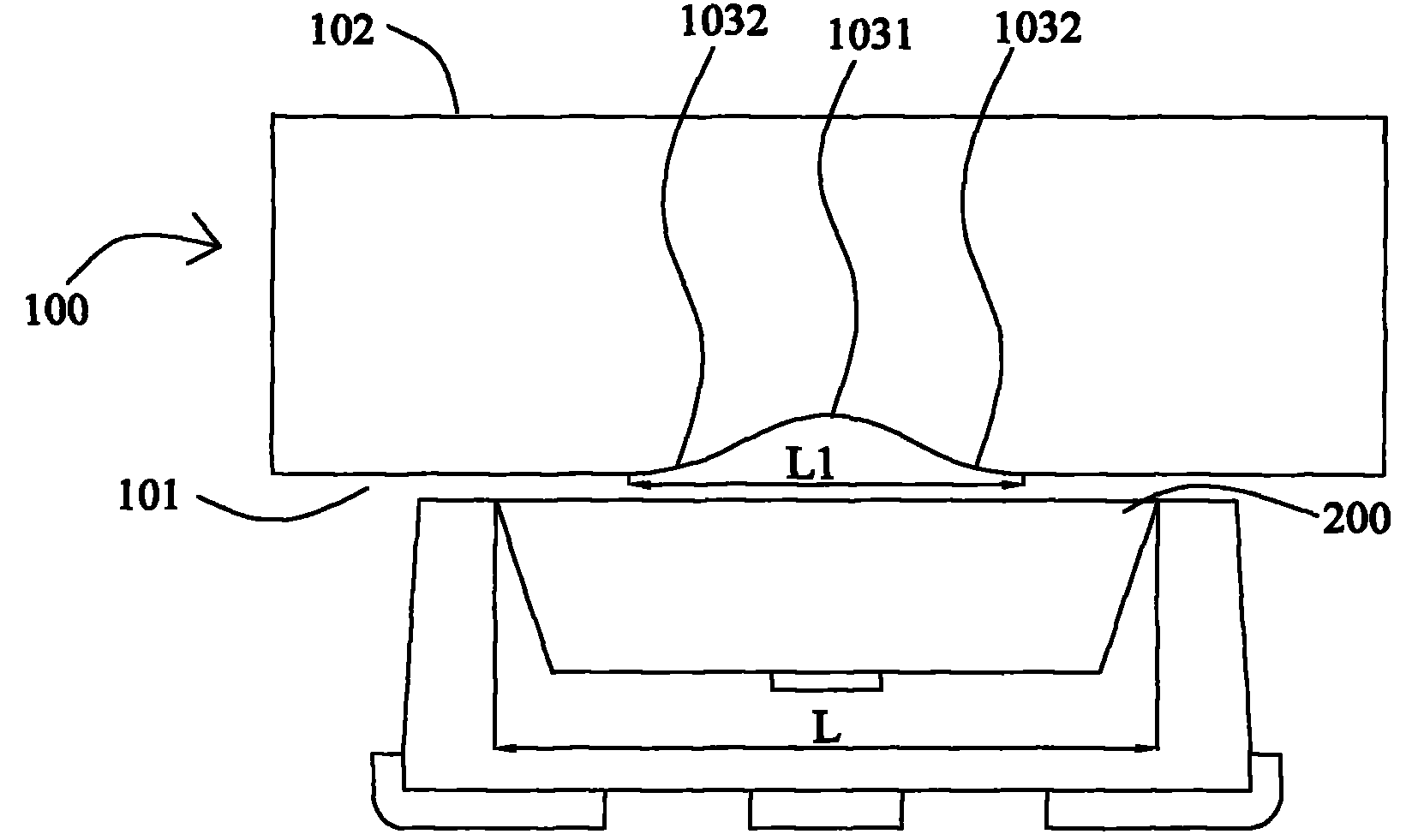
[0021] figure 1 It is a sectional view of the light incident structure of the light guide plate of the present invention, see figure 1 . In the light incident structure of the light guide plate of the present invention, the light guide plate 100 has a light incident surface 101 for receiving the light source of the illuminant, and a light exit surface 102 opposite to the light incident surface 101, and the light exit surface 102 is used for outputting the light emitted by the light source 200. , and the light source 200 is disposed on one side of the light incident surface 101 of the light guide plate 100 . The light incident surface 101 includes a first curved surface 1031 and a second curved surface 1032 , and the light emitted by the light source 200 passes through the first curved surface 1031 and the second curved surface 1032 before being output from the light exit surface 102 .

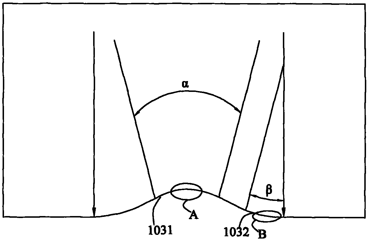
[0022] figure 2 It is a partial enlarged view of the cross-sectional view of the light ...


PUM


Abstract

The invention discloses a light guide panel. The panel comprises a light incidence surface and a light radiation surface, wherein the light incidence surface is provided with a first curved surface and a second curved surface; the first curved surface is arranged at a central position right above a light source and is an indented curved surface bending toward the center of the light guide panel; and the second curved surface is arranged at the periphery of the first curved surface and is a convex curved surface bending toward the light source. The first curved surface can scatter light at theposition where the brightness is highest and cause light to be distributed more uniformly, while the second curved surface can better concentrate the light at the position where the brightness is lower and add to the brightness of light. The coordination of the first and the second curved surface can uniformly scatter the light of a place with excessive brightness towards a surrounding place withlower brightness, thus increasing both the brightness and the uniformity of the whole light guide panel.

Description

technical field [0001] The present invention relates to a light guide plate, in particular to a light guide plate which can increase the overall brightness and light uniformity of the light guide plate. Background technique [0002] With the development of digital technology, liquid crystal display products have been widely used in all aspects of daily life. However, the liquid crystal itself does not emit light, and a light source device is required to continuously provide light to inject light into the liquid crystal display screen, so that the screen display can be realized. [0003] In the prior art, the backlight module usually makes a plurality of R-shaped notches on the light incident surface of the light guide plate on the side close to the light source, but this method has certain defects. The intensity of light from light-emitting diodes is caused by hot spots and glowing lines called pulsating shading and cat-eye phenomenon (eye phenomenon). The strength of the ...

Claims


Application Information

Patent Timeline
Patent Type & Authority Patents(China)
IPC IPC(8): G02F1/1335F21V8/00F21V13/00
Inventor 林慧玲蔡承翰廖永兴陈靖闳
Owner LITE ON OPTO TECH (CHANGZHOU) CO LTD
Features
  • R&D
  • Intellectual Property
  • Life Sciences
  • Materials
  • Tech Scout
  • Unparalleled Data Quality
  • Higher Quality Content
  • 60% Fewer Hallucinations
Learn More