Revolving electric device, and its manufacturing method

A technology for rotating electrical machines and manufacturing methods, applied in the direction of manufacturing motor generators, electromechanical devices, electrical components, etc., to achieve the effects of firm fixation, increased rated output, and stable contact

Active Publication Date: 2010-03-10
YASKAWA DENKI KK
View PDF4 Cites 23 Cited by
  • Summary
  • Abstract
  • Description
  • Claims
  • Application Information

AI Technical Summary

Problems solved by technology

[0014] This second prior art differs from Patent Document 1 in that it is not an induction motor, but a permanent magnet motor in which the stator coil 45 is collectively wound around one tooth portion 42b.

Method used


Image

  • Revolving electric device, and its manufacturing method
  • Revolving electric device, and its manufacturing method
  • Revolving electric device, and its manufacturing method

Examples


Embodiment 1

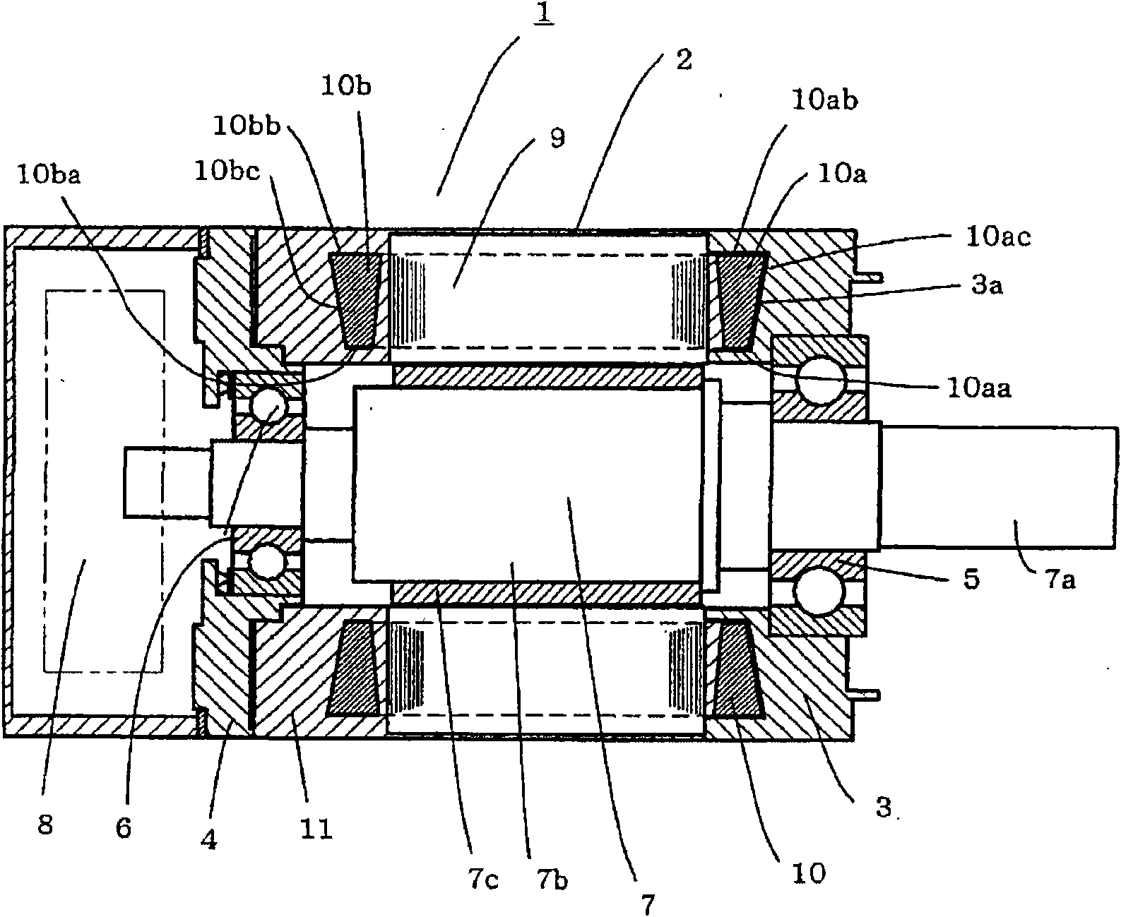
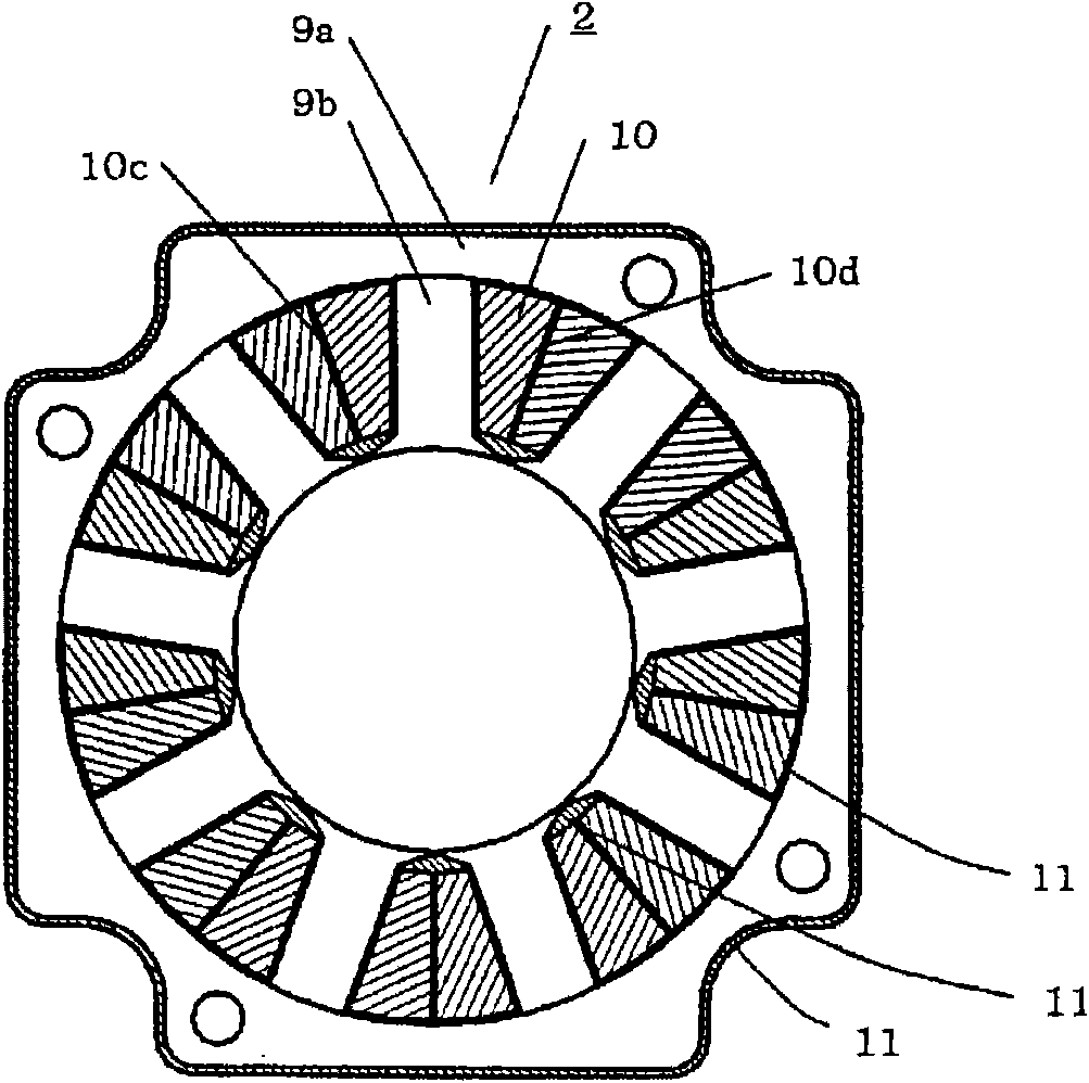
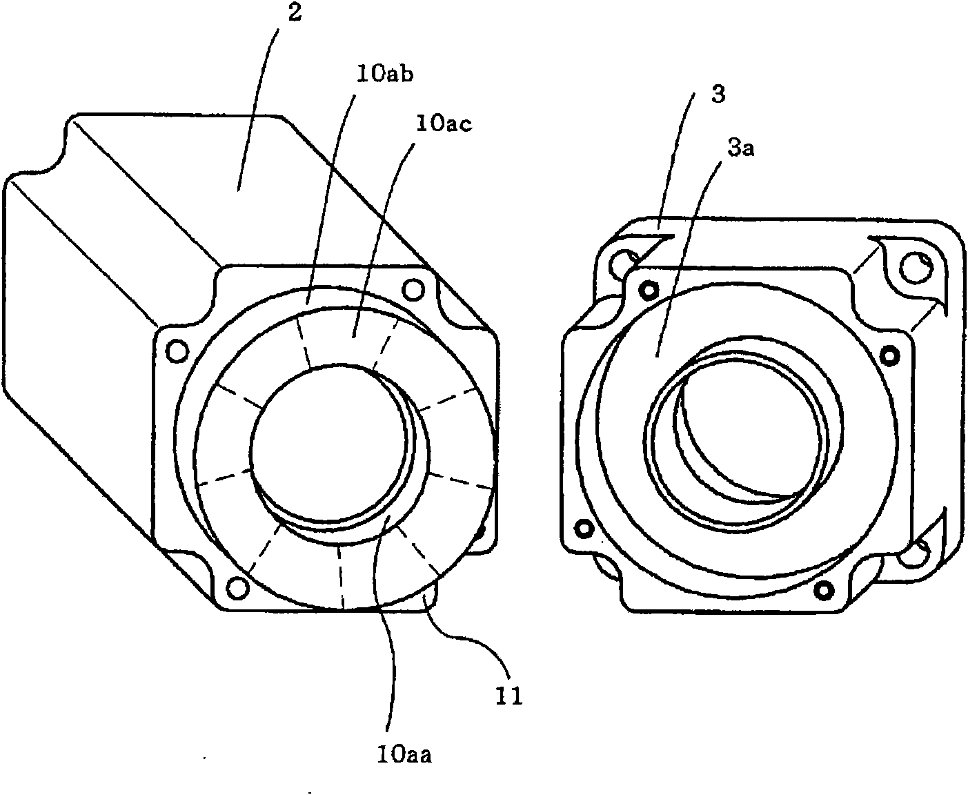
[0082] figure 1 It is a side test sectional view showing a rotating electrical machine such as a permanent magnet motor in the first embodiment of the present invention. figure 2 Yes figure 1 The front sectional view of the rotating electrical machine in , the rotor is omitted.

[0083] exist figure 1 and figure 2 Among them, 1 is a rotating electrical machine such as a permanent magnet motor, and includes: a stator 2; ; the opposite load side bracket 4 arranged on the opposite load side; the cylindrical shape having the rotating shaft 7a rotatably supported by the load side bracket 3 and the load opposite side bracket 4 through the bearings 5 ​​and 6 The rotor 7, and the rotation detector 8, such as an encoder, etc. which are arrange|positioned to the opposite load side than the said load opposite side bracket 4, etc. are comprised. 7b is a rotor core fitted to the said rotating shaft 40a, 7c is a permanent magnet attached to the outer peripheral surface of the said...


PUM


Abstract

A rotary electric motor includes a cylindrical rotor having an outer peripheral side, a stator provided to surround the outer peripheral side of the rotor with a gap between the stator and the rotor,and a load side bracket having a recess and provided on a load side of the stator. The stator includes stator coils and a stator core having teeth portions around which the stator coils are wound. A load side coil end of each of the stator coils protrudes from a load side end face of the stator core. At least two of an inner peripheral surface, an outer peripheral surface, and an end face of the load side coil end contact an inner surface of the recess via an insulator.

Description

technical field [0001] The present invention relates to a rotating electrical machine having a cylindrical rotor and a stator mounted with stator coils. Background technique [0002] Conventionally, in many rotating electrical machines having a cylindrical rotor and a stator to which stator coils are attached, heat generated in the stator coils wound around the teeth of the stator core passes through a frame provided on the outer periphery of the stator and a load side connected to the frame. The bracket is used to dissipate heat to the outside of the rotating electrical machine (for example, refer to Patent Document 1). [0003] Figure 12 It is a side cross-sectional view showing the first prior art, and is a structural example of a rotating electrical machine, such as an induction motor, including a cylindrical rotor and a stator having a stator coil wound around teeth of a stator core and attached. [0004] exist Figure 12 Among them, the rotating electrical machine 21...

Claims


Application Information

Patent Timeline
Patent Type & Authority Applications(China)
IPC IPC(8): H02K3/24H02K3/34H02K5/04H02K15/12
CPCH02K15/12H02K15/028H02K9/22H02K5/08H02K9/223
Inventor 野中刚
Owner YASKAWA DENKI KK
Why Eureka
Try Eureka