LAVAL pipe jet air stirring device

A technology of stirring device and Rafael tube, used in transportation and packaging, chemical instruments and methods, dissolution, etc., can solve problems such as easy damage of mechanical seals and slurry leakage, and achieve high reliability, fewer components, and reduced wear and tear. and the effect of corrosion

Inactive Publication Date: 2010-03-17
中建中环新能源有限公司
View PDF1 Cites 11 Cited by
  • Summary
  • Abstract
  • Description
  • Claims
  • Application Information

AI Technical Summary

Problems solved by technology

Another problem with the metal blade agitator is that the mechanical seal is easily damaged, which frequently causes slurry leakage accidents

Method used


Image

  • LAVAL pipe jet air stirring device
  • LAVAL pipe jet air stirring device

Examples


Embodiment Construction

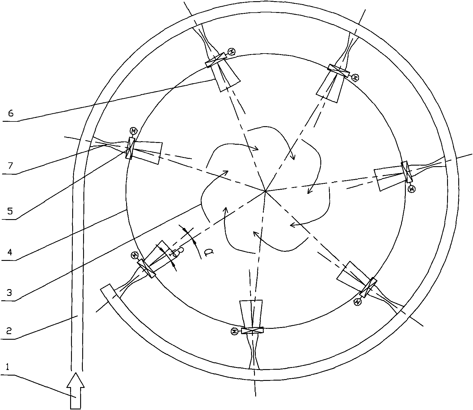
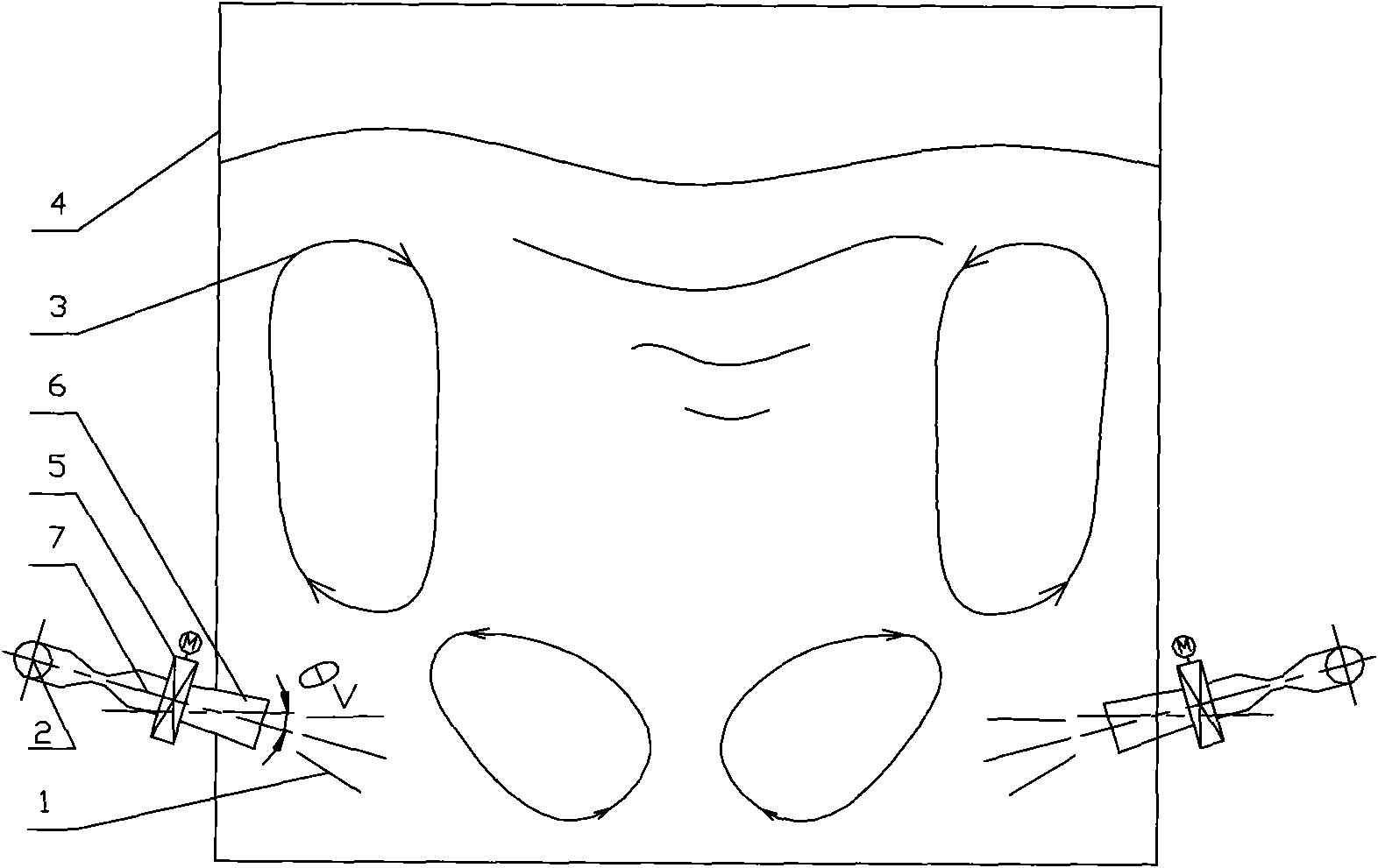
[0014] The Rafal tube jet air stirring device is composed of an air distributor 2 and a jet device, wherein the jet device is composed of a Rafal tube 7 , a valve 5 and a turbulence tube 6 . The air distributor is generally arranged on the peripheral wall of the slurry tank, and then the jet device is evenly arranged according to the diameter of the slurry tank.

[0015] Air or compressed air 1 is evenly distributed to each Rafal tube 7 through the air distributor 2, and the air is accelerated to the velocity V (10m / s

[0016] The role of valve 5 is to control the amount of injected air, thereby controlling the intensity of stirring, and in addition, it can also prevent the backflow of slurry d...


PUM


Abstract

The invention relates to an LAVAL pipe jet air stirring device used in a wet-process flue gas desulfurization system (WFGD) or similar fields for preventing sediment in a size tank. The device comprises a size tank, a plurality of eddy flow pipes arranged on the inner wall of the size tank, an air distributor, an LAVAL jet pipe and a valve, wherein the air outlet end of the LAVAL jet pipe is connected with the air inlet ends of the eddy flow pipes, the air inlet end of the LAVAL jet pipe is connected with the air outlet end of the air distributor, and the valve is arranged between the eddy flow pipes and the LAVAL jet pipe. The LAVAL jet pipe is used for accelerating jetting air with a certain pressure into the size, under the initial velocity and floatage, the air overturns and rises to drive size around to overturn so as to achieve the effect of stirring.

Description

technical field [0001] The invention relates to an air agitation device used in a wet flue gas desulfurization system (WFGD) or similar fields to prevent sedimentation in a slurry tank. Background technique [0002] The currently known agitator in this field to prevent the deposition of the slurry tank is a metal blade agitator, which is generally installed on the top of the tank, and the motor drives the metal shaft and the metal blade to rotate at a certain speed, and the blade stirs the slurry to prevent the solid particles in the slurry from depositing and hardening As a result, problems such as pipe blockage and slurry failure in the system are caused. [0003] The metal blade agitator system consists of a reducer, motor, bracket, support plate, mechanical seal, shaft, hub, blade, deflector arc plate, and blade lock nut. Since the desulfurization slurry contains a certain amount of chloride ions and other corrosive components, the material in contact with the slurry ne...

Claims


Application Information

Patent Timeline
Patent Type & Authority Applications(China)
IPC IPC(8): B01F13/02B01F33/40
Inventor 缪明烽张志平代旭东卢作基陈茂兵
Owner 中建中环新能源有限公司
Why Eureka
Try Eureka