Differential pressure oil supply structure of horizontal scroll compressor

A scroll compressor and compression mechanism technology, applied in the field of scroll compressors, can solve problems such as oil leakage, lack of oil wear, large load on movable scroll bearings and main bearings, etc., to reduce pressure drop and leakage, reduce The possibility of bearing wear and the effect of reducing the difficulty of assembly

Pending Publication Date: 2022-08-09
常熟英华特环境科技有限公司
View PDF1 Cites 0 Cited by
  • Summary
  • Abstract
  • Description
  • Claims
  • Application Information

AI Technical Summary

Problems solved by technology

[0003] The above structure has the following problems: the oil path through which the lubricating oil flows is too long, the pressure drop when the lubricating oil reaches the orbiting scroll bearing is too large, and there is a risk of leakage in the oil path; however, the orbiting scroll bearing and the main bearing are heavily loaded, The demand for lubricating oil is high, which leads to oil starvation wear of orbiting scroll bearings and main bearings when the compressor is under high load

Method used


Image

  • Differential pressure oil supply structure of horizontal scroll compressor
  • Differential pressure oil supply structure of horizontal scroll compressor
  • Differential pressure oil supply structure of horizontal scroll compressor

Examples


Embodiment Construction

[0045] The preferred embodiments of the present invention will be described in detail below with reference to the accompanying drawings.

[0046] The technical solutions in the embodiments of the present invention will be clearly and completely described below with reference to the accompanying drawings in the embodiments of the present invention. Obviously, the described embodiments are only a part of the embodiments of the present invention, but not all of the embodiments. Based on the embodiments of the present invention, all other embodiments obtained by those of ordinary skill in the art without creative efforts shall fall within the protection scope of the present invention.

[0047] The use of ordinal numbers "first," "second," "third," etc. to describe common objects merely refers to different instances of similar objects, and is not intended to imply that objects so described must have temporal, spatial, A given order in terms of sorting or in any other way.

[0048]...


PUM


Abstract

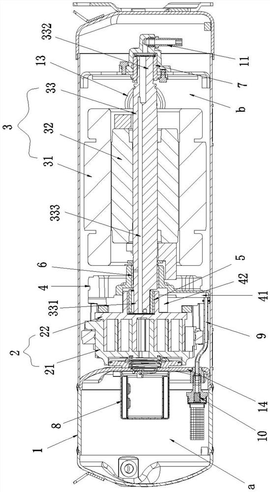
The invention discloses a differential pressure oil supply structure of a horizontal scroll compressor, the differential pressure oil supply structure comprises an oil-gas separation device and an oil return pipe, the oil-gas separation device is arranged in a high-pressure cavity and is arranged on the exhaust port side of a compression mechanism, and the oil-gas separation device is used for separating lubricating oil in exhaust gas of the compression mechanism and storing the lubricating oil in a high-pressure cavity oil pool; one end of the oil return pipe is communicated with the high-pressure cavity oil pool, and the other opposite end is communicated with an internal oil path of the main bearing seat; the thrust surface of the main bearing seat is in close contact with the bottom surface of the movable scroll plate to form a closed bearing cavity, the bearing cavity is respectively communicated with an internal oil path of the main bearing seat and an internal oil path on the crankshaft, the internal oil path of the crankshaft is communicated with a shaft head of the crankshaft and a shaft tail of the crankshaft, and lubricating oil can be transmitted to a low-pressure cavity oil pool from a bottom bearing at the shaft tail of the crankshaft. According to the scroll compressor, an oil way is greatly shortened, pressure drop and leakage in the oil way are reduced, the movable scroll bearing is always soaked in lubricating oil, and the possibility that the bearing is abraded during heavy-load operation of the compressor is reduced.

Description

technical field [0001] The invention belongs to the technical field of scroll compressors, and in particular relates to a differential pressure oil supply structure of a horizontal scroll compressor. Background technique [0002] The main internal structural difference between the horizontal scroll compressor and the vertical scroll compressor is its oil return system. The oil return methods of horizontal scroll compressors are generally divided into two types: oil pump oil supply and differential pressure oil supply. Application No. 202010648815.6 discloses an oil circulation structure of a horizontal scroll compressor, which throttles the lubricating oil in the high-pressure chamber and then presses it into the end of the crankshaft shaft to supply oil to each bearing. [0003] The above structure has the following problems: the oil path through which the lubricating oil flows is too long, the pressure drop when the lubricating oil reaches the movable scroll bearing is to...

Claims


Application Information

Patent Timeline
Patent Type & Authority Applications(China)
IPC IPC(8): F04C29/02F04C18/02
CPCF04C29/02F04C29/026F04C18/0215
Inventor 陆志远季晓炜王志豪
Owner 常熟英华特环境科技有限公司
Why Eureka
Try Eureka