Motion control sensor system for a moving unit and motion control system

A motion control and moving body technology, applied in the direction of brake system interaction, automatic steering control components, brakes, etc., can solve the problem of increased cost, and achieve the effect of reducing assembly man-hours and using materials

Inactive Publication Date: 2010-03-17
HITACHI CABLE
View PDF3 Cites 3 Cited by
  • Summary
  • Abstract
  • Description
  • Claims
  • Application Information

AI Technical Summary

Problems solved by technology

[0022] In the system researched and developed as a method of installing the sensor on the non-rotating part of the hub, since the temperature of the installation environment is high, when using the strain sensor method, it is necessary to perform sensitivity correction of other axes, and it is necessary to install multiple sensors , there is a problem of increased cost

Method used


Image

  • Motion control sensor system for a moving unit and motion control system
  • Motion control sensor system for a moving unit and motion control system
  • Motion control sensor system for a moving unit and motion control system

Examples


Embodiment Construction

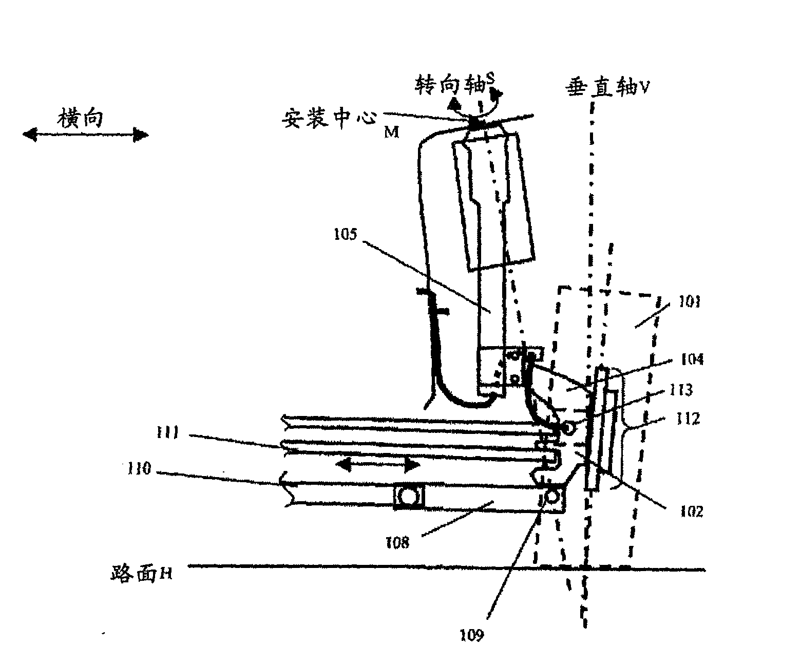
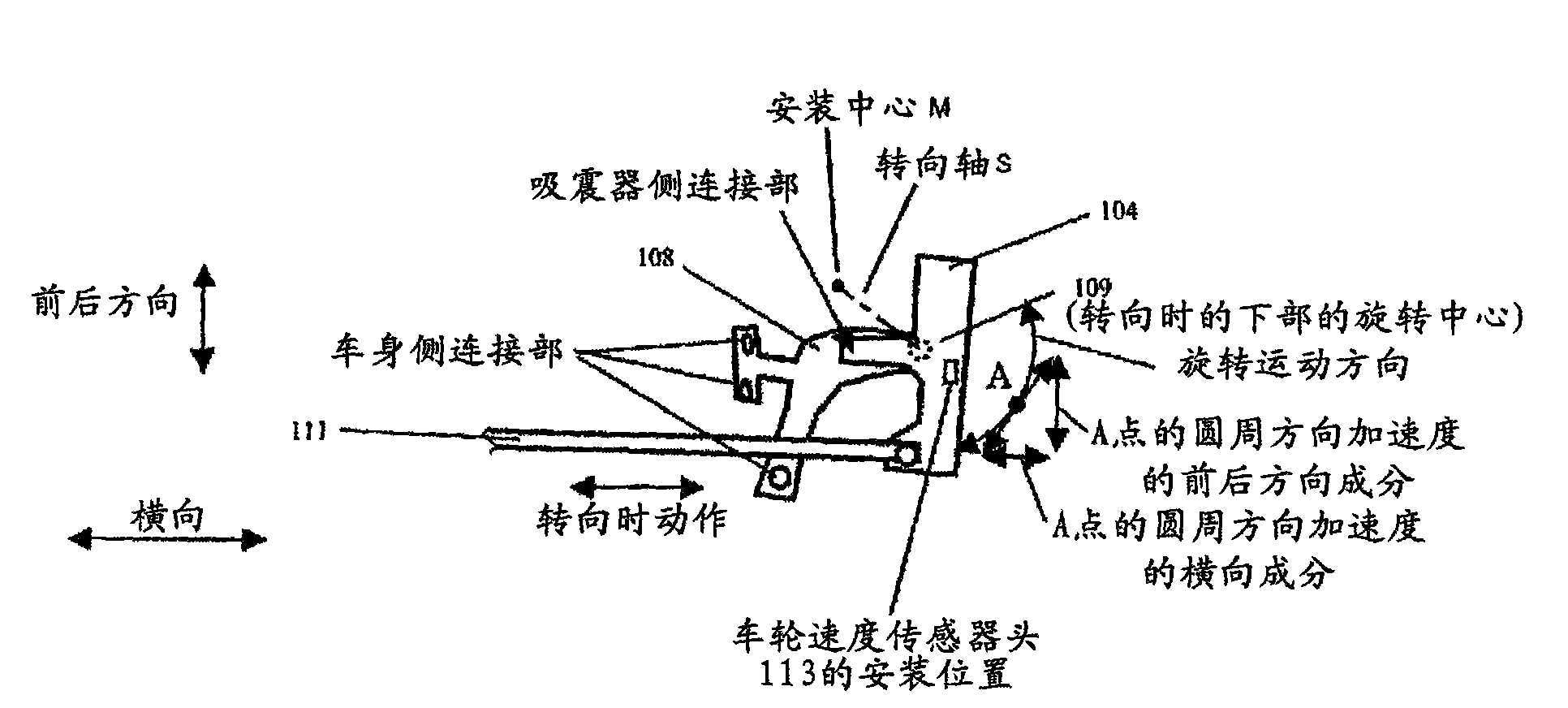
[0060] like figure 1 and figure 2 As shown, physical quantity sensors such as acceleration sensors and angular velocity sensors are installed "under the spring" of mobile bodies such as vehicles. Specifically, a physical quantity sensor (not shown) is mounted on the lower part of the shock absorber 105 or on the joint 104 rigidly connected to the lower part of the shock absorber 105 .

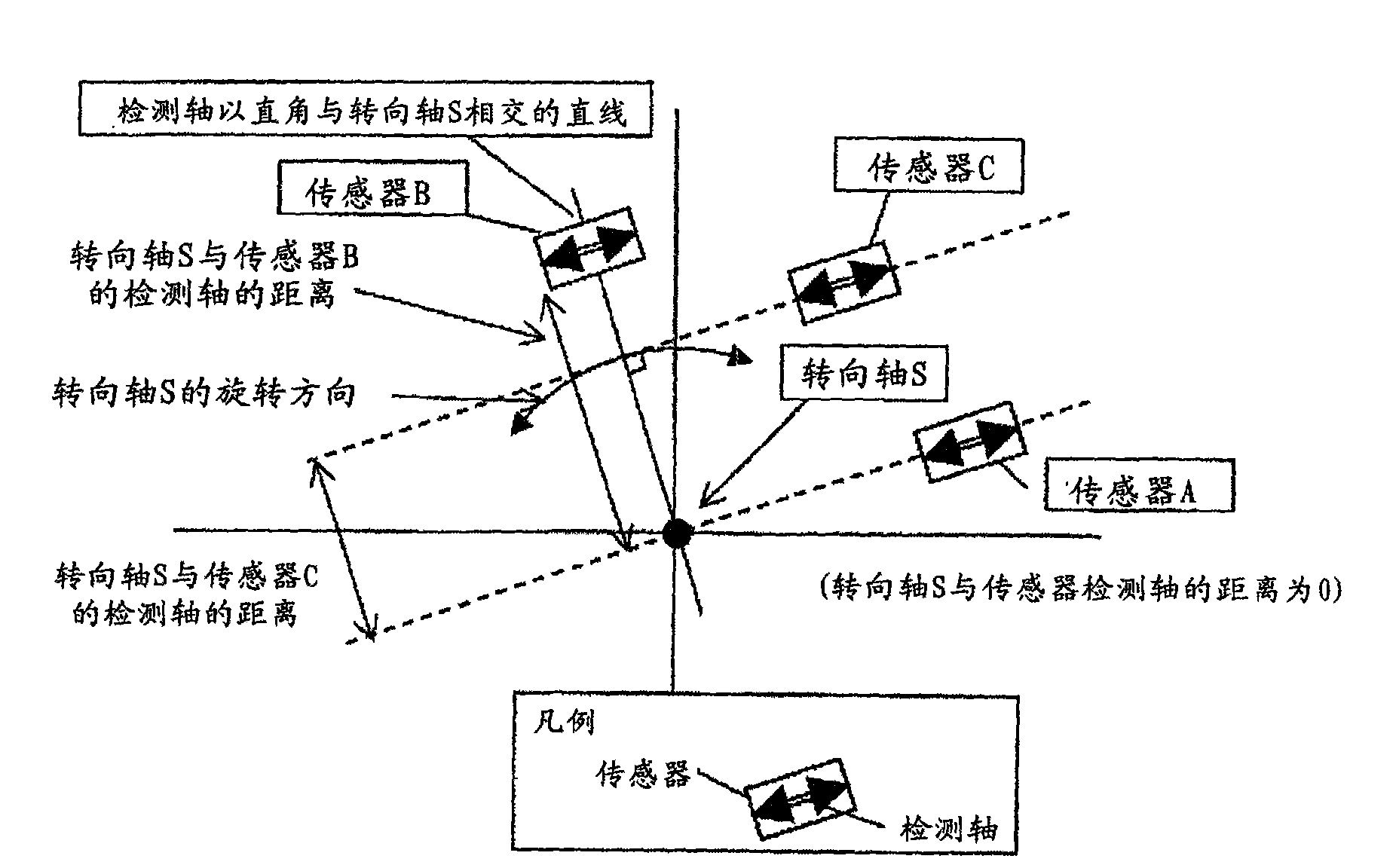
[0061] When the operation of the mobile body is performed, angular acceleration is also generated due to the rotational motion of the operation itself. Therefore, do not use the acceleration generated by this angular acceleration as the detection object of the acceleration sensor. For this purpose, the detection axis of the acceleration sensor is arranged to intersect with the operation axis generating angular acceleration. The intersection of the detection axis and the operation axis means that the detection axis and the operation axis are in the same plane, and the detection axis and the...


PUM


Abstract

A motion control sensor system and motion control system for a moving unit have a physical quantity sensor in an unsprung mass of the moving unit so that physical quantities in the unsprung mass can be detected, bypassing the spring. An acceleration sensor for detecting acceleration exerted on the unsprung mass of the moving unit is placed so that its detection axis crosses the operation axis of the moving unit, so acceleration due to angular acceleration around the operation axis is not detected. Accordingly, the motion control sensor system and motion control system are suitable for runningstability control during cornering of the moving unit.

Description

technical field [0001] The present invention relates to a sensor system for motion control of a mobile body and a motion control system suitable for driving stability control when the mobile body turns. Background technique [0002] For a long time, in order to improve the braking, driving performance (braking performance) and handling stability of the vehicle as a moving body, it has been developed to measure the movement of the vehicle, and according to the measurement results, the braking and driving of the vehicle and the movement of each wheel Manipulate the system for control. [0003] Anti-lock braking systems and traction control systems that suppress locking and slipping of individual wheels by using wheel speed sensors that detect rotational speeds of individual wheels of a vehicle are generally widespread. [0004] An existing motion control system installed with wheel speed sensors is shown in Figure 13 and Figure 14 . Figure 13 It is a view showing the vici...

Claims


Application Information

Patent Timeline
Patent Type & Authority Applications(China)
IPC IPC(8): B60W30/02G01P15/18B60R16/02B60T8/171B62D6/00G01P15/00
CPCB60G2400/0523B60G2400/208B60G2204/112B60G3/06B60G2204/202B60G2401/902B60G2400/1042B60G2204/113B60T2260/06B60G15/07B60T8/171B60G2200/142B60G2204/115
Inventor 山本哲
Owner HITACHI CABLE
Why Eureka
Try Eureka