
Motor vehicle driver assisting method near the stability limit

A technology for drivers and motor vehicles, which is applied in the field of assisting motor vehicle drivers, and can solve problems such as drivers becoming easily bored and low activation thresholds

Inactive Publication Date: 2010-03-17
GM GLOBAL TECH OPERATIONS LLC
View PDF6 Cites 11 Cited by
  • Summary
  • Abstract
  • Description
  • Claims
  • Application Information

AI Technical Summary

Problems solved by technology

[0003] The inherent dilemma in conventional ESC systems is the fact that the driver expects them to be active and reliable in critical situations, thus having a noticeable effect on the movement of the vehicle, but, on the other hand, if the ESC system is useful to him- Or at least intervene in a situation he believes he can handle himself, and the driver tends to become bored
In order for the ESC system to be as intrusive as possible, its activation threshold would have to be set rather high, thus leading the driver into a problematic situation where harsh measurements of the ESC system are necessary, which This situation could have been easily prevented by using a lower activation threshold

Method used


Image

  • Motor vehicle driver assisting method near the stability limit
  • Motor vehicle driver assisting method near the stability limit
  • Motor vehicle driver assisting method near the stability limit

Examples


Embodiment Construction

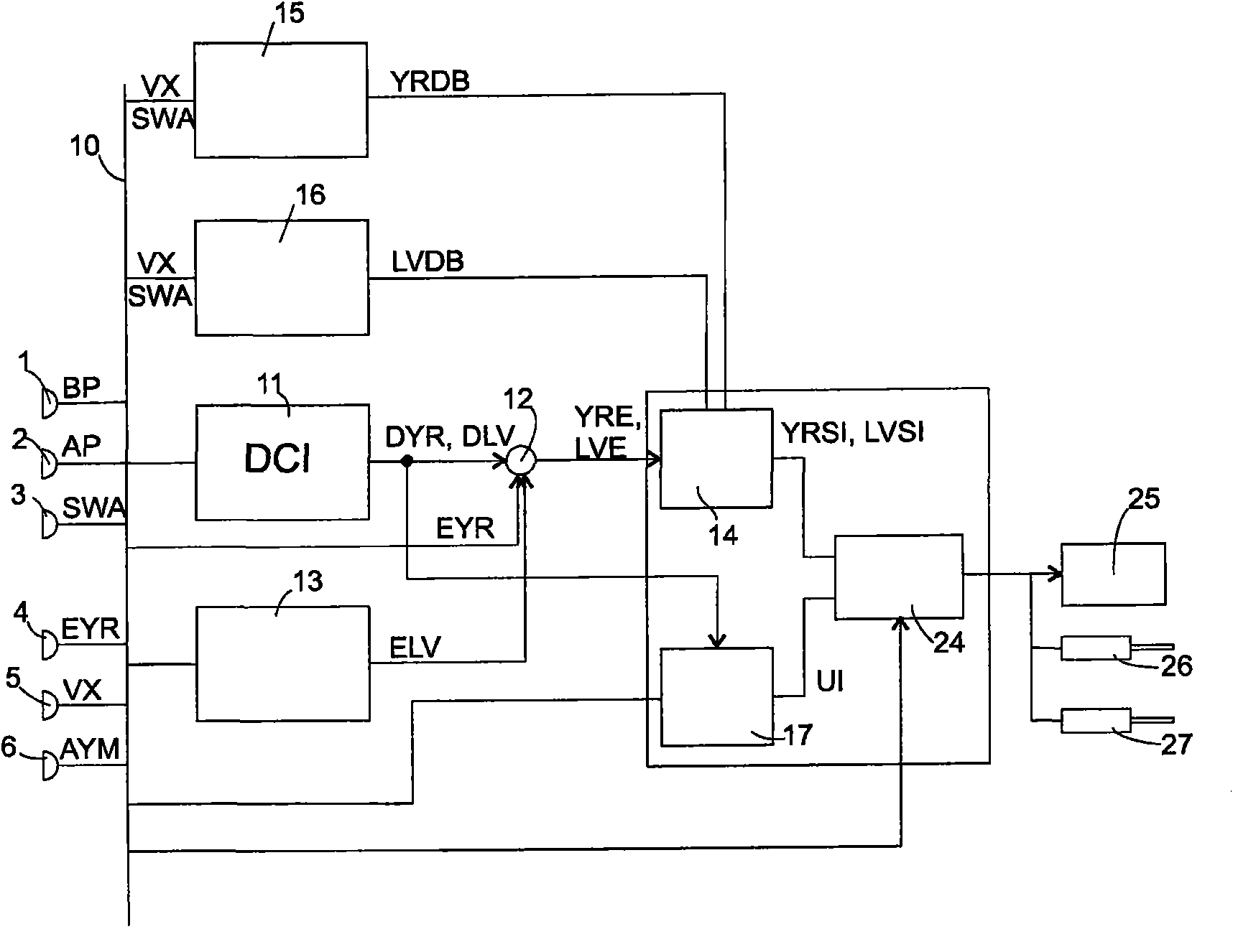
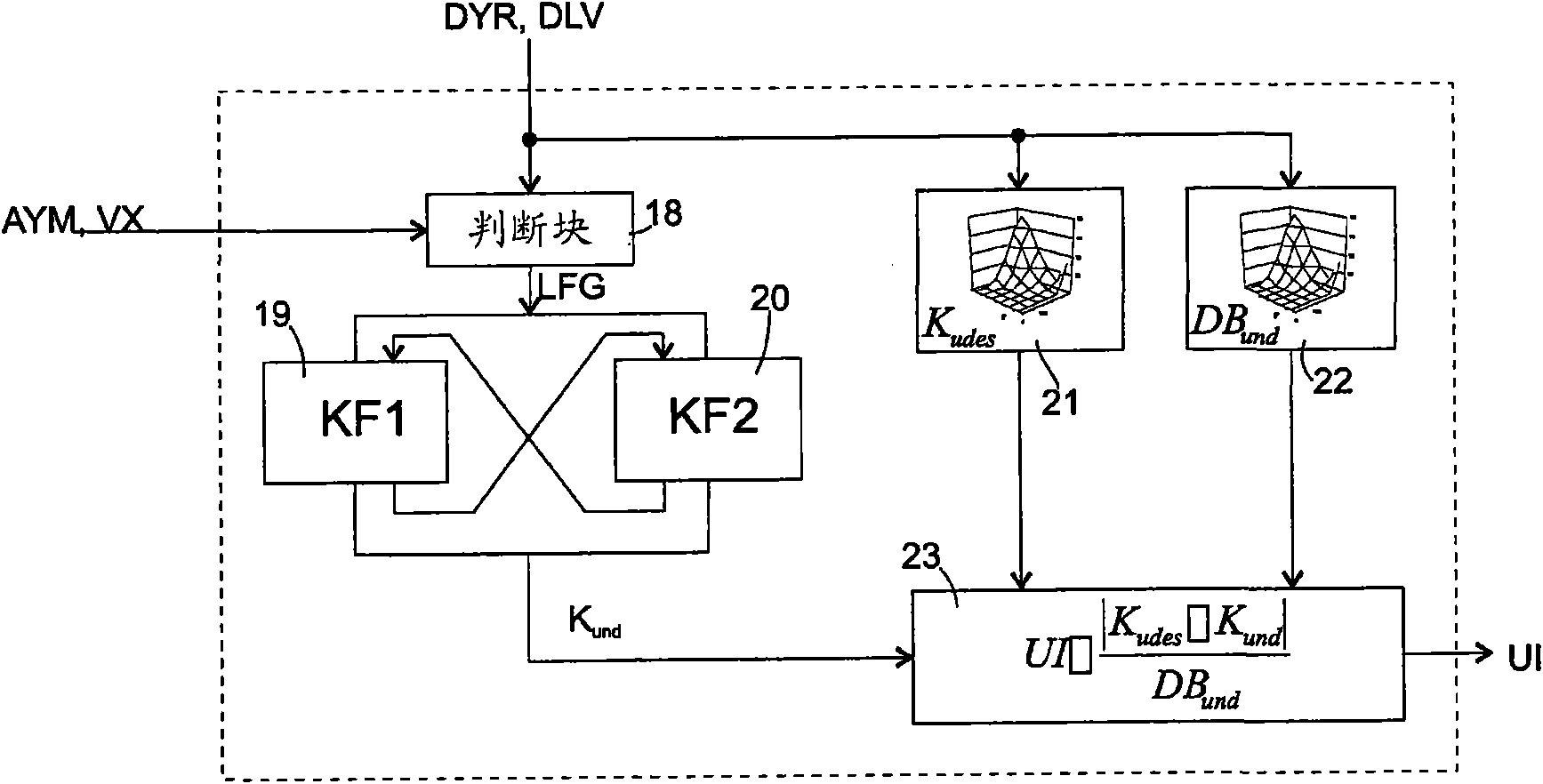
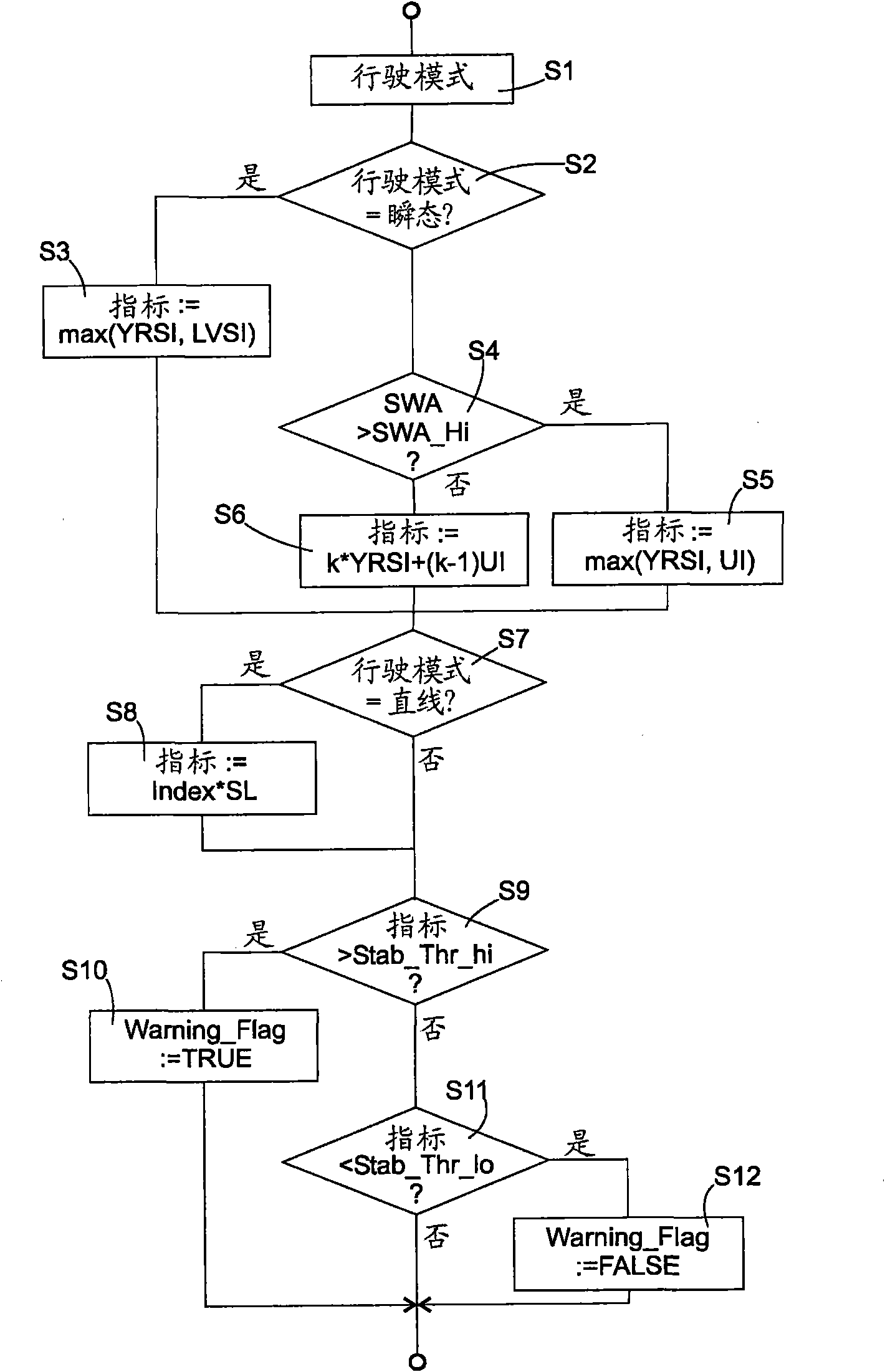
[0025] In order to correctly understand the following description, it should be kept in mind that the present invention will most likely be implemented in the form of a reasonably programmed microcontroller system, but the function of running as software in such a microcontroller system may also be realized by wiring circuits. Therefore, the description of the present invention based on the circuit blocks or the individual characteristics of the method steps is not specified by technical necessity but simply by the fact that in the case of simultaneous execution of the process or the time relationship of the process does not affect the present invention , The description through the block diagram is easier to understand than the flowchart. On the contrary, if the steps can be concisely organized in chronological order, the description of the method steps through the flowchart is more clear.

[0026] figure 1 It is a block diagram of the device used to implement the present inventi...


PUM


Abstract

A method for assisting a driver of a motor vehicle comprises the steps of a) monitoring at least one quantity selected among vehicle sideslip, yaw rate error, understeer and quantities correlated to vehicle sideslip, yaw rate error or understeer, b) deciding that there is a risk of the vehicle becoming unstable if any of said monitored quantities or a quantity derived (S3, S5, S6) from one or more of said monitored quantities exceeds a predetermined first threshold (S9); and c) if it is decided that there is a risk, issuing a warning signal (S10).

Description

Technical field [0001] The present invention relates to a method of assisting a motor vehicle driver to improve driving safety in potentially dangerous road conditions. Background technique [0002] In recent years, electronic stability control systems for motor vehicles have gradually become popular. Traditionally, such systems monitor the vehicle stability-related quantities, such as the yaw rate deviation (ie, the deviation between the desired yaw rate based on the vehicle speed and steering wheel angle and the observed yaw rate), and to assist corners Cornering to apply braking to one wheel of the vehicle respectively, that is, to reduce the deviation between the expected and the observed yaw rate. [0003] The inherent dilemma in traditional ESC systems is the fact that the driver expects them to become active and reliable in critical situations, thus having a significant effect on the movement of the vehicle, but, on the other hand, if the ESC system is able to- Or at least...

Claims


Application Information

Patent Timeline
IPC IPC(8): B60W30/02B60W10/06B60W10/18B60W40/10
CPCB60T8/1755B60Q9/00
Inventor 尤塞夫·戈内姆
Owner GM GLOBAL TECH OPERATIONS LLC
Learn More